基于可变相位延迟的激光干涉式亚纳米级微位移测量系统
刘通1,2, 张刘1,*, 张冠宇1, 陈晨1,*, 仲志成1
1. 吉林大学仪器科学与电气工程学院, 地球信息探测仪器教育部重点实验室, 吉林 长春 130061
2. 吉林大学机械科学与工程学院, 吉林 长春 130022
*通讯联系人 E-mail: cchen@jlu.edu.cn; zhangliu@jlu.edu.cn

作者简介: 刘 通, 1984年生, 吉林大学仪器科学与电气工程学院讲师 E-mail: tongliu@jlu.edu.cn

摘要

激光光源具有单色性好、 亮度高、 方向性强和相干性强等优势, 所以基于干涉原理对激光光谱进行积分可以应用于微位移测量领域。 在重力方法探测过程中, 因地质结构不同引起万有引力差异而造成的探测质量块位移十分微小, 通常为纳米级, 所以研制高精度纳米级微位移测量系统尤为重要。 然而传统电容位移测量法在防止电磁干扰等方面存在不足。 相比较而言, 光学干涉法具备抗电磁干扰、 环境适应性强等优点, 且精度不亚于电容法。 传统干涉系统光路复杂、 难于集成, 对重力仪的小型化与集成化不利。 所以研制一种结构紧凑的光学干涉系统用于实现纳米级微位移测量成为亟需。 基于可变相位延迟的激光干涉式方法, 能够实现亚纳米级微位移测量, 较传统干涉系统具备结构紧凑、 易于集成的优势。 本微位移测量系统由半导体激光器、 起偏器、 检偏器、 楔形双折射晶体组和光谱仪组成。 研究从以下方面展开: 首先是确定测量系统方案, 提出了偏振光干涉双路结构, 以楔形双折射晶体组作为核心器件, 将晶体间相对位移转化为o光和e光的差别化相位延迟, 并对激光光谱进行积分, 进而将位移变化转变为合成光强的变化; 其次是建立测量位移物理模型, 根据设计的双折射晶体组几何结构、 位移过程与光路, 确定光强变化与待测位移量之间的关系; 第三是系统参数优化, 为了使系统的测量误差和量程满足实际需求, 利用已建立的物理模型, 将测量误差和量程分别与晶体切割角度 α、 激光器激射波长 λ建立函数关系。 根据应用需求, 确定适当的误差和量程取值范围, 进而得到角度 α和波长 λ取值范围; 最后加工晶体、 搭建系统并进行测试。 具体即以 α λ为调控参量, 联合考虑“近似线性化”和“激光器光强波动误差”对系统量程进行优化仿真。 同样, 联合考虑“激光器光强波动误差”和“激光器波长波动误差”, 并利用“系统最大位移量”(与量程有关)对系统测量误差进行优化仿真。 最终确定钒酸钇晶体切割角度 α为20°, 激光器激射波长 λ为635 nm。 实验中, 以10 nm为间隔利用压电陶瓷设置位移量进行位移测试, 包括: 系统的线性标定、 系统量程和测量误差测试。 另外, 在保持待测位置不变的条件下, 利用本位移测量系统进行了2 h不间断测量, 并通过阿伦方差确定了系统的位移探测下限。 实验结果表明, 位移量程范围大于150 nm, 位移测量误差约0.5 nm, 位移探测下限为0.32 nm@23 s, 探测线性度判定系数( R2)为0.999 85。 综上所述, 以自制楔形双折射晶体组作为核心器件的可变相位延迟激光干涉式微位移测量系统, 可作为重力探测中的质量块位移测量单元。 与电容法相比具有更强的环境适应性; 与传统干涉系统相比具有结构简易、 光路紧凑等优点, 便于重力仪的小型化与集成化。

关键词: 重力测量; 微位移测量; 可变相位延迟; 激光干涉; 双折射晶体组
中图分类号:O59 文献标志码:A
A Laser Interferometric Subnano-Scale Micro-Displacement Measurement System Based on Variable Phase Retardation
LIU Tong1,2, ZHANG Liu1,*, ZHANG Guan-yu1, CHEN Chen1,*, ZHONG Zhi-cheng1
1. Key Laboratory of Geophysical Exploration Equipment, Ministry of Education, College of Instrumentation & Electrical Engineering, Jilin University, Changchun 130061, China;
2. School of Mechanical Science and Engineering, Jilin University, Changchun 130022, China
Abstract

Laser has many advantages in good monochromatic, high brightness, strong directional and good coherence. Therefore, the integral of laser spectrum can be applied to the field of micro displacement measurement, which is based on the interference principle. In the process of gravimetry, gravity differences caused by different geological structures make the micro nano-scale displacements of detection mass. Therefore, development of micro displacement measurement system with nanometer precision is vital. However, traditional capacitance displacement measurement method (CDMM) is not sufficient to prevent electromagnetic interference. In comparison,the optical interference method (OIM) has the advantages of anti-electromagnetic interference,strong environmental adaptability,and higher precision than CDMM. For the traditional OIM system, the optical path is complex and difficult to integrate, which is unfavorable to the miniaturization and integration of the gravimeter. Therefore, developing a compact OIM system to measure the micro displacement with nanometer precision has become an urgent requirement. A laser interferometric method based on variable phase retardation was designed to achieve sub-nanometer resolution displacement measurement, which has the advantage of compact structure and easy integration compared to traditional OIM system. This system was composed with diode laser, polarizer, analyzer, birefringent crystal group and spectrometer. This paper studies the following aspects: firstly, the measurement system scheme is determined. The structure with dual optical path of polarized light interference is introduced, and the wedge birefringent crystal group is used as the core device, which transforms relative displacement among crystals into differential phase delay between ordinary light (o) and extraordinary light (e). Integrate the laser spectrum,and then the displacement change is transformed to the variance of the synthesis light intensity. Secondly,the physical model of displacement measurement is set. According to the design of birefringent crystal group geometry structure,displacement process and optical path, the relationship between light intensity variance and measured displacement is determined. The third is the optimization of system parameters. In order to make the system measurement error (ME) and measurement range (MR) to meet the practical requirements, using the established physical model, the ME and the MR are set up as a function of crystal cutting angle α and laser wavelength λ. According to application requirements, appropriate bounds of ME and MR is determined, and then α and λ is obtained. Finally, crystal process, systems build and the system measurement test were carried out. In detail, α and λ are chosen as control parameters to optimize and simulate the system, jointly considering “approximate linearization” and “laser intensity fluctuation error”. Meanwhile, jointly considering “laser wavelength fluctuation error” and “laser intensity fluctuation error”, and using the maximum displacement related to system MR, to optimize system ME. Eventually, yαis selected as 20 ° and λ is 635 nm. In testing experiments, displacement measurement is carried out by means of piezoelectric ceramic actuator generating micro-displacement with 10 nm intervals, which includes linear calibration, MR and ME of the system. In addition, a two-hour continuous measurement is carried out using this system when measured position is fixed, and the displacement detection limit is determined by Allan variance. Experimental results show that the displacement MR is longer than 150 nm, and displacement ME is around 0.5 nm, and a detection limit is 0.32 nm @23 s, and the linearity determination coefficient R2 is 0.999 85. In conclusion, the system using self-made birefringent crystal group as the core device with adjustable phase retardation can be used as the displacement measurement unit of mass in gravity detection. This system has the advantage of strong environmental adaptability compared with CDMM, and laconic structure and compact light path compared with the conventional laser interference system, so as to facilitate the miniaturization and integration of the gravimeter.

Keyword: Gravimetry; Micro-displacement measurement; Variable phase retardation; Laser interference; Birefringent crystal group
引 言

激光干涉式微位移测量法属于非接触式微位移测量。 常用非接触式微位移测量方法包括: 电容式[1, 2]、 光学式[3, 4, 5, 6, 7]等。 电容式传感器的分辨率目前已达到pm量级[2], 然而电容传感易受到温度、 湿度以及寄生电容的影响[8, 9, 10], 当应用在如舰船平台这样的复杂环境中时, 其性能受到限制。 光学式测量方法主要包括激光干涉法[3, 4]、 光学三角法[5, 6]等。 虽然激光干涉法的分辨率已达pm量级[4], 但其光路复杂、 难于集成。 光学三角法虽广泛应用于原子力显微镜中[5, 6]。 但在测量过程中, 待测物的微小偏转会对测量结果造成极大影响。

本文提出了一种基于可变相位延迟的激光干涉式方法, 通过引入楔形双折射晶体组, 实现了o光和e光的差别化相位延迟, 并对激光光谱进行积分, 进而将位移变化转变为最终合成光强的变化。 本位移测量系统与传统激光干涉法相比具有结构简易、 光路紧凑、 稳定性高、 精度高等优势, 便于重力仪的小型化与集成化。

1 位移测量基本原理
1.1 测量光路与光强变化规律

图1为本位移测量系统的核心光路示意图, 图中部件1、 2组成双折射晶体组, P1和P2为两个偏振器, 其偏振化方向互相垂直。 其中P1的偏振方向与双折射晶体光轴方向夹角为θ 。 显然A2o=A2e=Asinθ cosθ

图1 位移测量系统核心光路示意图Fig.1 Schematic diagram of core optical path of position measurement system

A表示A2oA2e的合成振幅, 则有

A2(Δδ)=A2o2+A2e2+2A2oA2ecos2πΔδλ(1)

其中Δ δ 表示振幅为A2oA2e两光矢量的光程差, λ 表示激光器激射波长。 而光强I正比于 A2δ ), 所以可通过测量光强I的变化, 进而测量总光程差Δ δ 的变化。

本位移测量系统选取θ 为45° , 则光强I可表示为

I=I01+cos2πΔδλ(2)

其中I0为光程差Δ δ = 14λ 时, 位移测量系统的输出光强。

1.2 位移量与光程差Δ δ 之间关系

如图1所示, 组件1固定, 当组件2的位移量为L时(定义两组间相互靠近时位移为正), e光对o光的光程差对应发生变化, 具体如式(3)

Δδ=δe-δo=2L[(ne-no)tanα-11-ne2sin2α-11-no2sin2αsinα+ne21-ne2sin2α-no21-no2sin2α-ne-nocosαsin3α](3)

其中α 为钒酸钇晶体切割角度, 故将光程差Δ δ 定义为晶体切割角度的函数f(α )与位移量L的乘积, 即

Δδ=f(α)L(4)

故:

I=I01+cos2πf(α)Lλ(5)

即由光强I的变化测得位移量L

2 理论分析及模拟仿真
2.1 系统量程优化仿真

α λ 为调控量。 从式(5)光可以看出, 测量结果符合余弦曲线变化规律, 在小范围内可近似为线性, 则要求这种“ 近似线性化” 所引起的误差小于激光器光强波动误差(0.07%)的90%(比例系数90%为实验经验值), 具体表达见式(6)

-2πf(α)Lλ+π2-cos2πf(α)Lλ1+cos2πf(α)Lλ×0.07%×90%(6)

解此不等式, 求得取不同α λ 时对应的L取值范围, 即系统量程。 仿真结果如图2所示。

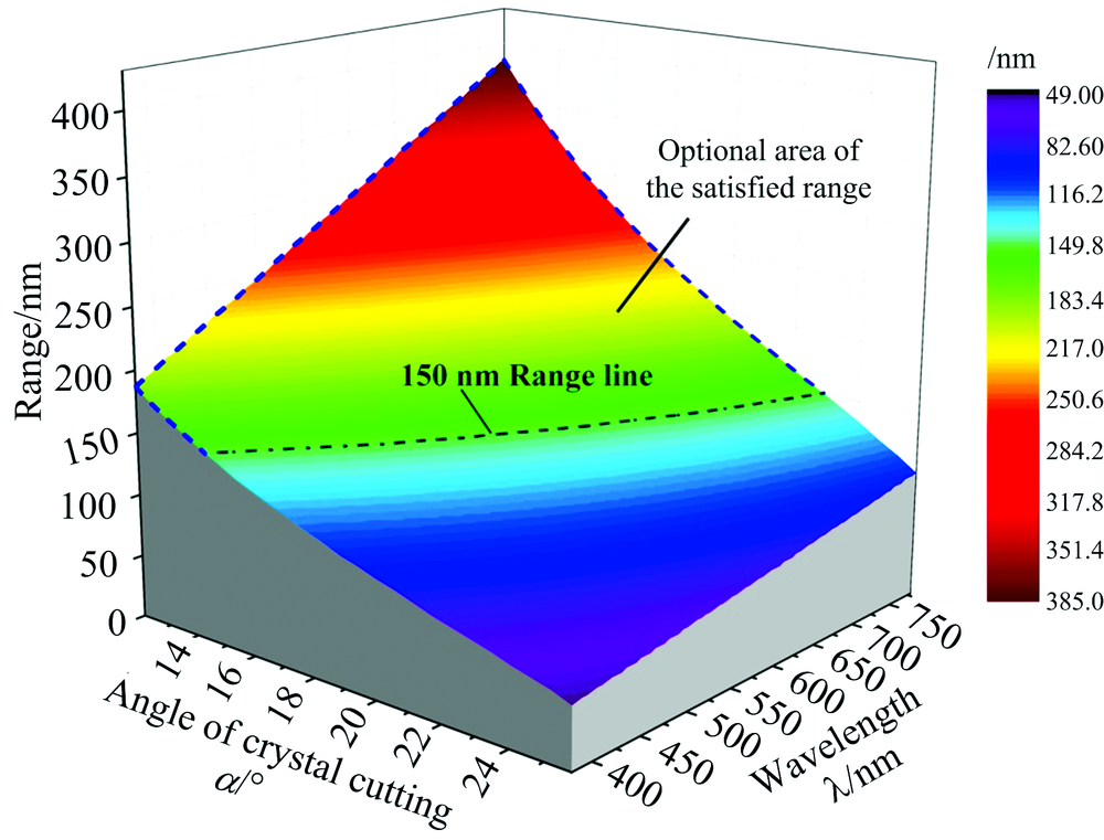
图2 系统量程与晶体切割角度α 和激光器激射波长λ 对应关系Fig.2 Range of the nanometer measurement versus α and λ

考虑到钒酸钇晶体加工工艺的因素, 仿真中取12° < α < 26° , 考虑到激光器的成本和小型化因素, 仿真中的激光器激射波长λ 取可见光波段。 由于实际需求(详细叙述见2.3), 量程需要大于150 nm(图2中虚线所圈范围)。

2.2 系统位移测量误差优化仿真

在待选量程范围内, 待测位移与光强近似符合线性

I=I0-2πf(α)Lλ+π2+1(7)

L=λ2πf(α)-II0+1+π2(8)

考虑激光器的光强波动误差 |ΔI|I0和波长波动误差 |Δλ|λ, 则位移误差|Δ L|可表示为

|ΔL|=λ2πf(α)|ΔI|I0+L|Δλ|λ(9)

取各情况L的最大值, 即

|ΔL|λ2πf(α)|ΔI|I0+Lmax|Δλ|λ(10)

可求得取不同α λ 时对应测量误差|Δ L|的上限值。 需要指出, 该测量误差的估算只考虑了两个主要因素, 激光器光强波动误差(0.07%)和波长波动误差(0.008%), 其他可对位移测量造成较小影响的因素并未考虑。 仿真结果如图3所示。

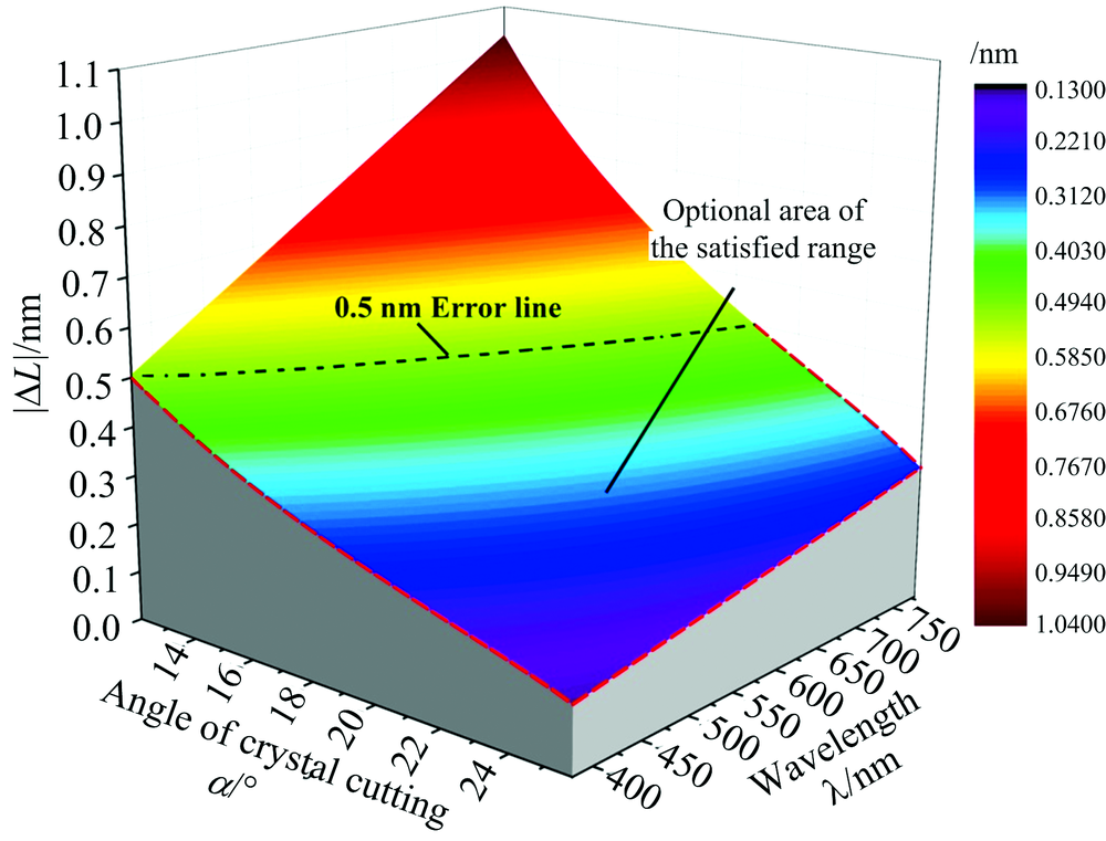
图3 系统位移测量误差与晶体切割角度α 和激光器激射波长λ 对应关系Fig.3 Displacement measuring error versus α and λ

与2.1相同, 取12° < α < 26° , λ 取可见光波段进行仿真。 由于实际需求(详细叙述见2.3), 测量误差需要小于0.5 nm(图3中虚线所圈范围)。
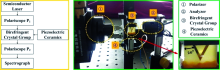
2.3 位移测量方案确立

以研制的超导重力梯度仪[7]为项目目标, 选择位移测量误差≤ 0.5 nm[1, 11]。 由于每月产生相当于50 nm的零点漂移量[12], 所以选择位移量程大于150 nm, 以保证两次测量落在量程范围以内。 综合以上两方面分析, 参数的选取应位于图4中两条临界线圈定的区域之内。 方案最终确定为图4中红点对应位置(α = 20° , λ =635 nm), 对应系统的理论测量误差0.43 nm、 理论量程158 nm。

图4 具体实验参数选择Fig.4 Selection of specific parameters in the experiment

3 位移测量系统

位移测量系统结构框图如图5(左)所示。

图5 位移测量系统构架示意图(左)和局部实物照片(右)Fig.5 Schematic diagram (left) & Photo (right) of the displacement measurement system

激光光源激射中心波长为635 nm, 光强波动小于0.07%, 波长波动小于0.008%。 P1和P2两个偏振器均为GT5-A格兰-泰勒偏振器, 波长窗口为350~700 nm。 为了提高分辨率, 且考虑到成本因素, 实验中自制的楔形双折射晶体采用了非寻常光折射率ne和寻常光折射率no之差较大且容易获得的钒酸钇晶体材料加工而成。 选用HR4000高分辨率微型光纤光谱仪, 测量范围为600~660 nm, 光学分辨率达到0.02 nm。 实验中待测位移由带有闭环控制的压电陶瓷实现, 其定位精度为0.5 nm。 如图5(右)中为该位移测量系统核心部分的实物照片, 从照片中可以看出楔形双折射晶体的切割角度为20° 。

4 实验部分

实验一开始, 先将半导体激光器预热, 按设计光路依次通过偏振器P1、 双折射晶体组、 偏振器P2, 最后用光谱仪接收, 并对光强进行积分。 控制闭环压电陶瓷进行定量位移, 记录位移量和相对光强, 不断重复多次, 便可求得位移与光强对应关系。

4.1 位移测量误差及稳定度

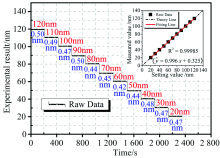
每过一段时间以10 nm为间隔、 递减方式设置位移量, 进行光强采集, 测量结果如图6所示。

图6 系统以10 nm间隔的时域位移测量结果(主图)及其对应测量值的线性拟合(右上子图)Fig.6 Time series of the measured displacement by the increments of 10 nm & the linear fitting line according to the displacement measured (the small graph in the upper right)

设定位置标注于各台阶上方, 位移实测值与设定值存在偏差。 其中, 当设定值为110 nm时, 偏差最大(0.58 nm), 最大偏差优于理论量程的 0.37%。 此外, 在各台阶下方标注了各设定位置测量值的标准差, 实验中该值最大为0.50 nm, 出现在设定值120和90 nm处。

同时, 将位移测量数据进行线性拟合, 结果如图6中子图所示。 图中, 黑色方形点为各设定位置的测量值均值, 红色实线为实测数据(方形点)的拟合线, 虚线为理想状态下的设置与实测对应线。 可以看出所测位移数据整体保持线性规律。 通过线性拟合, 实测位移数据线性度判定系数R2=0.999 85。 此处, 线性度判定系数R2的定义为

R2=1-i=1n(yi-y˙i)2i=1n(yi-y̅)2(11)

其中, y˙i为线性拟合函数(见图6)在各点处的取值, yi为各点位移测量值, y̅yi平均值。

4.2 位移测量下限

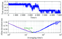
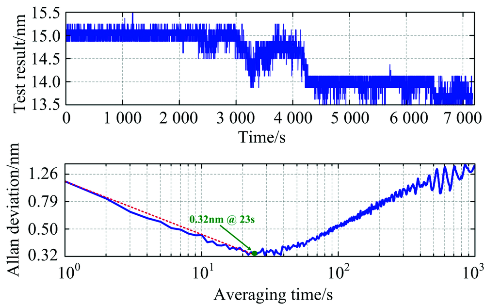
实验中, 在保持待测位置不变的条件下, 利用本位移测量系统进行两小时不间断测量, 结果如图7所示。

图7 基于稳定性测量数据(a)以平均时间为自变量的阿伦方差曲线(b)Fig.7 Allan deviation plot as a function of averaging time (a) based on the measurement data (b)

从图7(a)可以看出, 在2 h工作过程中, 位移测量波动范围2 nm。 同时, 图7(b)给出了位移系统随平均测试时间变化的阿伦(Allan)方差计算结果。 可以看出, 在测量平均时间为23 s时, 位移测量系统性能最佳, 位移测量下限为0.32 nm。

此外, 从位移测量系统长时间测量数据存在一定漂移, 这是由于其采用单探测光路所导致的。 后续工作拟采用双光路差分探测架构, 抑制系统长期漂移共模噪声, 从而提高测量系统长期工作稳定性。

5 结 论

该测量系统中通过引入楔形双折射晶体组, 达到o光和e光的差别化相位延迟, 并对激光光谱进行积分, 进而将位移变化转变为最终合成光强的变化, 实现了基于可变相位延迟的激光干涉式亚纳米级微位移测量。 该位移量程范围大于150 nm, 位移测量误差约0.5 nm, 位移探测下限为0.32 nm @23 s, 探测线性度判定系数(R2)为0.999 85。 与传统激光干涉系统相比, 本系统具有结构简易、 光路紧凑等优点, 能够实现质量块高精度位移测量, 在重力仪的小型化与集成化方面具有良好的应用潜能。

The authors have declared that no competing interests exist.

参考文献
[1] XU Jing-wen, WANG Hui, HU Xin-ning, et al(胥靖文, 王晖, 胡新宁, ). Cryogenics & Superconductivity(低温与超导), 2016, 44(4): 1. [本文引用:2]
[2] Wang W, Bao Y, Niu L, et al. Revista de la Facultad de Ingeniería U. C. V, 2017, 32(10): 276. [本文引用:2]
[3] Guan J, Köchert P, Weichert C, et al. Precision Engineering, 2017, 50: 114. [本文引用:2]
[4] Weichert C, Köchert P, Köning R, et al. Measurement Science and Technology, 2012, 23(9): 094005. [本文引用:3]
[5] Qin C, Zhang H J, Xu R, et al. Journal of Physics: Conference Series, 2016, 680(1): 012009. [本文引用:3]
[6] Yong Y K, Fleming A J, Reza Moheimani S O. IEEE/ASME Transactions on Mechatronics, 2013, 18(3): 1113. [本文引用:3]
[7] ZHAO Wen-cheng, XU Xian-ze, LIU Pan-pan, et al(赵文成, 许贤泽, 刘盼盼, ). Spectroscopy and Spectral Analysis(光谱学与光谱分析), 2017, 37(2): 659. [本文引用:2]
[8] Santo Zarnik M, Belavic D. Radioengineering, 2012, 21(1): 201. [本文引用:1]
[9] Anouti M, Timperman L. Phys. Chem. Chem. Phys. , 2013, 15(17): 6539. [本文引用:1]
[10] Hayati M, Sheikhi A, Grebennikov A. IEEE Transactions on Power Electronics, 2015, 30(8): 4404. [本文引用:1]
[11] Tu L C, Wang Z W, Liu J Q, et al. Review of Scientific Instruments, 2014, 85(9): 095108. [本文引用:1]
[12] JIA Jian-gang, LUAN Wei, SHEN Wen-bin(贾剑钢, 栾威, 申文斌). Geomatics and Information Science of Wuhan University(武汉大学学报·信息科学版), 2015, 40(10): 1366. [本文引用:1]