


左/右圆极化波操控的多功能太赫兹超表面
[蒋铭阳 , 李九生
, 李九生* , 郭风雷]
, 李九生, 郭风雷]
|
|


作者简介: 蒋铭阳, 2000年生, 中国计量大学太赫兹研究所硕士研究生 e-mail: 1422727607@qq.com
太赫兹波是指频率位于0.1~10 THz之间的电磁波, 介于微波和红外之间, 具有穿透力强、 分辨率高、 无电离辐射等优势, 在安全检测、 医学诊断、 材料分析等领域有广泛应用前景。 太赫兹技术发展与应用对太赫兹波多功能调控器件的需求日益增长, 传统介质在太赫兹波段响应微弱, 超表面因其能够在波长尺度对太赫兹波进行调控, 而且在加工和设计方面具有低成本、 小体积等优势, 受到研究人员广泛关注。 目前已报道超表面太赫兹功能器件, 或多或少存在着功能单一, 而且受单一偏振波限制。 当前, 研究人员提出方案主要是改变亚波长超表面结构的几何形态和排列方式引入传输相位或通过旋转单元结构引入几何相位实现对电磁波参数调控, 但是单种调控方式仍然存在可调谐性差等问题, 因此设计基于传输相位和几何相位理论协同调控的超表面电场调控器件显得更具前瞻性和意义。 引入一种全新对角双十字结构超表面, 该超表面单元结构由顶层金属图案、 中间介质层和底层金属板组成, 结合传输相位与几何相位协同作用, 完成对左圆偏振波和右圆偏振波独立调控。 在频率为1.1 THz的左/右圆偏振波入射时, 该超表面展现出多种功能, 包括不同拓扑荷数的涡旋波束、 波束分束、 涡旋波分束、 聚焦波束等。 这种创新结构设计为多功能、 多偏振的太赫兹调控器件研究提供了崭新的思路, 为太赫兹无线通信领域的应用场景提供了潜在的可能性, 同时也为太赫兹技术的不断发展提供了强大的推动力。 在未来的研究中, 可以通过改变超表面尺寸将其进一步拓展到微波和光学领域。
Terahertz waves are electromagnetic waves with frequencies between 0.1 and 10 THz, between microwave and infrared, with strong penetration, high resolution, no ionizing radiation, and other advantages, which have a wide range of application prospects in the fields of safety detection, medical diagnosis, material analysis and so on. The demand for Terahertz technology development and application of terahertz wave multifunctional modulation devices is growing. The traditional medium in the terahertz band response is weak; the metasurface, because of its ability to modulate the terahertz wave at the wavelength scale and in the processing and design of low-cost, small volume and other advantages by the researchers are widely concerned. Terahertz functional devices with metasurface have been reported to have more or less single functions and are limited by a single polarisation wave. Researchers propose that the program is mainly to change the geometric morphology and arrangement of the sub-wavelength metasurface structure to introduce the transmission phase or the geometric phase through the rotating unit structure to achieve the electromagnetic wave parameter tuning. However, a single tuning method still exists due to poor tunability and so on, and therefore, the design of the metasurface electric field tuning device based on the synergistic tuning of the transmission and geometric phase theory seems more prospective and meaningful. In this paper, a new diagonal double-cross structure metasurface is introduced, which consists of a top metal pattern, an intermediate dielectric layer, and a bottom metal plate and combines the synergistic effect of the transmission phase and geometrical phase to complete the independent tuning of the left circularly polarised wave and the right circularly polarised wave. At the incident of left/right circularly polarised waves with a frequency of 1.1 THz, the metasurface exhibits a variety of functions, including vortex beams, beam splitting, vortex wave splitting, and focusing beams with different topological charges. This innovative structural design provides a new idea for researching multi-functional and multi-polarisation terahertz modulation devices. It offers potential application scenarios in the field of terahertz wireless communication. Future research can extend it to the microwave and optical fields by changing the metasurface dimensions.
超表面由二维平面内周期排列的亚波长人工电磁超材料结构组成, 在波前调控方面有着突出的优势, 而且在加工和设计上具有灵活性、 低成本、 小体积等优势, 因此受到研究人员广泛关注。 近年来, 超表面通过控制入射电磁波的振幅、 相位、 偏振状态[1, 2, 3]等实现超透镜[4, 5, 6]、 异常反射或折射[7, 8, 9]、 全息成像[10, 11, 12]、 涡旋波束[13, 14, 15]等功能。 上述超表面的排布主要通过改变亚波长结构的几何形态和排列方式引入传输相位或通过旋转单元结构引入几何相位实现对电磁波参数调控。 2021年, Luo等[16]基于几何相位法设计了I形状和十字形组成复合超表面结构实现波束偏转、 扩散散射和涡旋波束产生等多种功能。 2022年, Li等[17]基于几何相位理论设计了对称双箭头超表面结构实现拓扑荷数l=-2的轨道角动量(orbital angular momentum, OAM)单波束、 双波束和四波束分束功能。 同年, 汪静丽等[18]基于传输相位设计了十字架金属结构与二氧化钒复合超表面产生拓扑荷数分别为l=+1和l=+2的两分束与四分束涡旋。 2023年, Li等[19]基于传输相位理论提出十字椭圆全硅太赫兹超表面产生球面波和涡流波叠加态和多通道传输。 上述分析表明, 分别采用传输相位、 几何相位理论设计的超表面电场调控器件已经取得一定进展, 但是已报道的超表面仍然存在功能单一、 可调谐性差等问题, 因此, 设计基于传输相位和几何相位理论协同调控的超表面显得更具前瞻性和意义。
本文设计了对称双十字超表面结构, 结合传输相位与几何相位协同作用, 完成对左圆偏振波和右圆偏振波独立调控, 在太赫兹波段分别实现不同拓扑荷数的涡旋波束、 波束分束、 涡旋波分束、 聚焦波束等功能, 该超表面为实现太赫兹多功能调控器件设计提供了新途径。
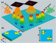
提出一种超表面结构及功能示意如图1所示。 图1(b)和(c)分别为超表面单元的三维图和俯视图, 其中单元结构由顶层两个长轴为a短轴为b的金属图案、 中间介质层和底层金属板组成。 顶层金属图案和金属底板材料为金, 厚度为1 μ m。 中间介质层材料为聚酰亚胺, 厚度为20 μ m, 顶层金属图案是位于主对角线上。
 | 图1 超表面功能与单元结构图 (a): 超表面的功能示意; (b): 单元结构三维图; (c): 俯视图Fig.1 Functional schematic and unit cell diagram of the proposed metasurface (a): Functional schematic diagram; (b): Three-dimensional diagram of the unit cell; (c): Top view of the unit cell |
当入射波垂直入射到超表面时, 对应的反射波电场可以表示为
式(1)中,
式(2)中, φ R和φ L分别为反射左圆偏振波(left circularly polarized, LCP)和右圆偏振波(right circularly polarized, RCP)相位, φ R=φ x-2α , φ L=-φ x-2α 。 综上所述, 利用传输相位和几何相位对左右圆偏振波进行解耦得到式(3)[20]
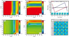
仿真得到频率1.1 THz处x偏振波和y偏振波入射下单元结构的反射振幅和反射相位响应。 图2(a—d)表示x(y)偏振波入射下反射振幅rxx(ryy)、 反射相位φ xx(φ yy)与顶层金属图案十字尺寸a和b取值关系。 图2(e)可以看出七个不同尺寸单元相位覆盖超过315° , 并且
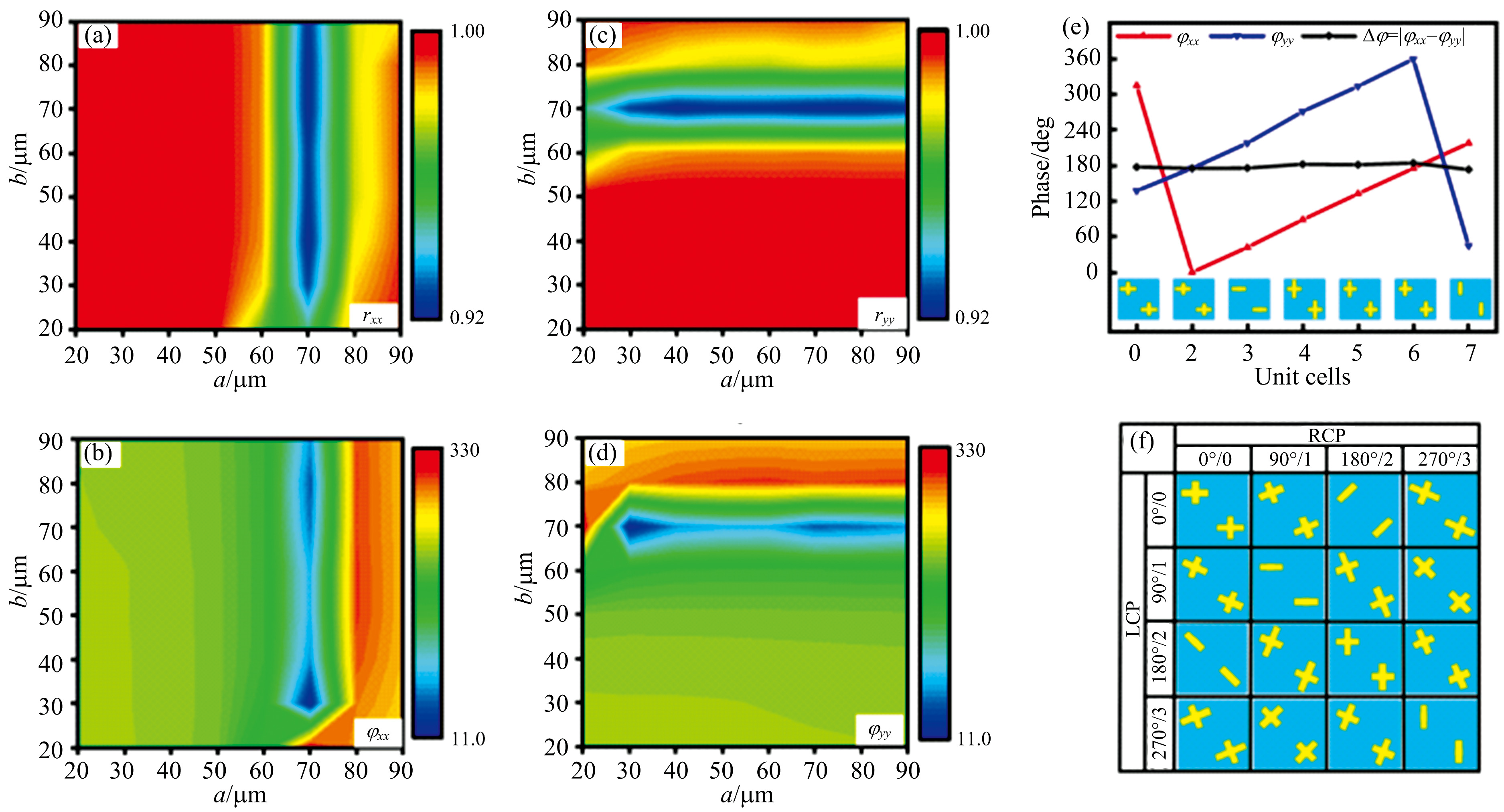 | 图2 超表面单元仿真结果 x偏振波入射下, 不同单元尺寸(a)反射振幅, (b)反射相位; y偏振波入射下不同单元尺(c)反射振幅, (d)反射相位; (e)线偏振波入射下七种编码单元相位变化曲线; (f)圆偏振波入射所需的16种编码单元; 0° /0、 90° /1、 180° /2和270° /3, 其中“ /” 前后分别为RCP(LCP)入射下的相位以及对应编号Fig.2 Simulation results of the encoding particles (a) Reflected amplitude, (b) Reflected phase of different unit cell under x polarized wave incidence; (c) Reflected amplitude, (d) Reflected phase of different unit cell under y polarized wave incidence; (e) Phase curves of seven kinds of unit cells under linear polarization wave incidence; (f) 16 kinds of unit cells for circularly polarized wave incidence; 0° /0, 90° /1, 180° /2, and 270° /3, before and after “ /” denotes RCP (LCP) incidence, respectively |
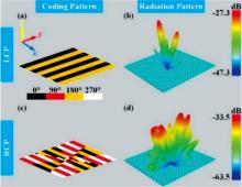
当LCP波入射时产生拓扑荷数l1=+1涡旋波束对应的超表面相位排布如图3(a)所示, 当RCP波入射时产生拓扑荷数l2=+2涡旋波束对应的超表面相位排布如图3(c)所示。 产生可切换涡旋波束超表面相位排布满足式(4)关系
式(4)中, φ L1和φ R1为超表面在LCP波和RCP波入射下产生不同拓扑荷数涡旋波束所需的相位排布。 频率1.1 THz的LCP和RCP太赫兹波入射到超表面分别产生拓扑荷数为l1=+1和l2=+2的涡旋波束, 其三维远场辐射如图3(b)和(d)所示。
 | 图3 超表面相位排布和功能示意图 (a): LCP波入射产生l1=+1的涡旋波束超表面相位排布; (b): 涡旋波束三维远场辐射; (c): RCP波入射产生l2=+2涡旋波束超表面相位排布; (d): 涡旋波束三维远场辐射Fig.3 Functional schematic and phase arrangement diagram (a): Phase arrangement of vortex beam metasurface with topological charge of l1=+1 under left-circularly polarized wave incidence; (b): Three-dimensional far-field radiation diagram; (c): Phase arrangement of vortex beam metasurface with topological charge of l2=+2 under right-circularly polarized wave incidence; (d): Three-dimensional far-field radiation |
图4(a)和4(b)表示LCP波入射下超表面产生拓扑荷数为l1=+1的涡旋波束电场强度和相位分布, 涡旋波束图案在不同拓扑荷数的中心具有甜甜圈状轮廓和振幅, 符合OAM涡旋波束的远场特性, 此时该涡旋波束的模式纯度为76.3%, 如图4(e)所示。 同样地, 图4(c)和(d)表示RCP波入射下超表面产生拓扑荷数为l2=+2的涡旋波束电场强度和相位分布, 其电场强度和相位分布符合OAM涡旋波束的远场特性, 且模式纯度为76.0%。 计算结果表明, 所设计的超表面可以通过切换入射波偏振态, 产生不同拓扑荷数涡旋波束调控。
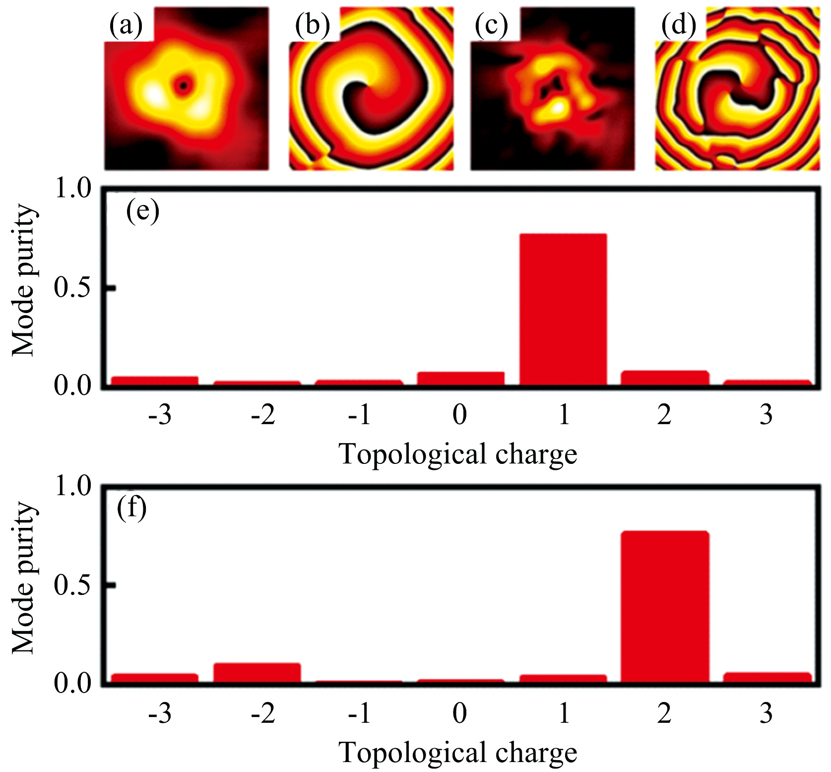 | 图4 LCP波入射下超表面产生拓扑荷数为l1=+1涡旋波束: (a) 电场强度分布, (b) 相位分布; RCP波入射下超表面产生拓扑荷数为l2=+2涡旋波束: (c) 电场强度分布, (d) 相位分布; (e) 拓扑荷数为l1=+1涡旋波束的模式纯度, (f) 拓扑荷数为l2=+2涡旋波束的模式纯度Fig.4 For LCP waves incidence, the proposed metasurface generates vortex beam with topological charge of l1=+1: (a) electric field intensity distribution, (b) phase distribution; For RCP waves incidence, the proposed metasurface generates vortex beam with topological charge of l2=+2: (c) electric field intensity distribution, (d) phase distribution; (e) Mode purity of the vortex beam with topological charge of l1=+1, (f) Mode purity of the vortex beam with topological charge of l2=+2 |
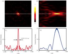
要实现LCP和RCP波入射到超表面分别实现分束和分束涡旋波, 该超表面所需相位分布如图5(a)和5(c)所示。 LCP太赫兹波入射时, 超表面相位排布序列为‘ 000222…’ (编码周期Г 1=1 200 μ m); RCP太赫兹波入射时, 超表面相位排布序列为 ‘ 0022…’ (编码周期Г 2=800 μ m)。 当频率为1.1 THz的LCP太赫兹波入射到超表面产生沿x轴方向的分束波束, 三维远场辐射结果如图5(b)所示。 相同频率的RCP太赫兹波入射到超表面产生沿y轴方向的拓扑荷数l=-1分束涡旋波, 三维远场辐射如图5(d)所示。 图6表示分束和分束涡旋远场辐射归一化曲线, 可以看出LCP太赫兹波入射时, 该超表面产生沿x轴方向的分束波偏转角为12.3° , 根据理论公式θ =arcsin(λ /Γ )计算得到分束偏转角为13.1° 公式, 与仿真结果相符。 当RCP太赫兹波入射时, 该超表面产生沿y轴方向拓扑荷数l=-1的分束涡旋波, 偏转角为19.2° , 根据分束偏转角理论θ =arcsin(λ /Γ )计算得到分束涡旋波偏转角为19.9° , 也与仿真结果相吻合。
 | 图5 超表面产生分束和分束涡旋波的相位排布及其远场辐射 LCP波入射, 超表面产生沿x轴方向分束波: (a)相位排布, (b)远场辐射; RCP波入射, 超表面产生沿y轴方向拓扑荷数l=-1分束涡旋波: (c)相位排布, (d)远场辐射Fig.5 The phase arrangement and far-field radiation of beam splitting and beam splitting vortex waves generated by the metasurface For LCP wave incidence, the metasurface generates beam splitting waves along x-axis: (a) phase arrangement, (b) far-field radiation; For RCP wave incidence, the metasurface produces splitting vortex beam with topological charge number of l=-1 along y-axis direction: (c) phase arrangement, (d) far-field radiation |
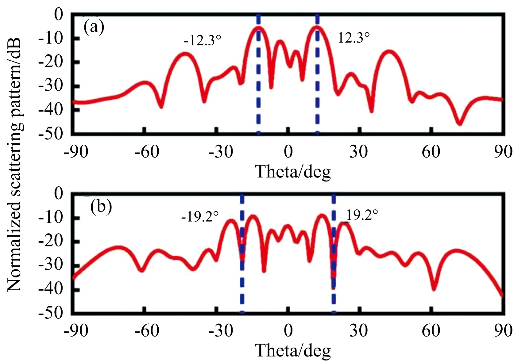 | 图6 分束和分束涡旋波远场辐射归一化曲线 (a): LCP波入射产生分束的归一化曲线; (b): RCP波入射产生分束涡旋波的归一化曲线Fig.6 Normalized far-field radiation curves of beam splitting and splitting vortex beam (a): The normalized scattering curve of beam splitting generated by LCP wave incidence; (b): The normalized scattering curve of splitting vortex beam generated by RCP wave incidence |
不同偏振波入射下产生不同焦距聚焦波束的超表面相位排布需要满足式(5)关系
式(5)中, 波长λ ≈ 272.7μ m, φ L2和φ R2为设计的超表面在LCP波和RCP波入射下产生不同聚焦距离聚焦波束所需的相位排布, 如图7(a)和图7(c)所示。 当LCP太赫兹波入射, 在该超表面上方f1=2 000 μ m处产生三维聚焦波束如图7(b)所示; 当RCP太赫兹波入射, 在该超表面上方f2=1 000 μ m处产生三维聚焦波束如图7(d)。
 | 图7 不同偏振波入射下, 超表面的相位排布和聚焦效果图 LCP太赫兹波入射, 超表面上方f1=2 000 μ m处产生聚焦波束: (a)相位排布, (b)聚焦三维图; RCP太赫兹波入射, 超表面上方f2=1 000 μ m处产生聚焦波束: (c)相位排布, (d)聚焦三维图Fig.7 Phase arrangement and focusing effect of the proposed metasurfaces under different polarization wave incidence For LCP wave incidence, the metasurface generates focused beam at f1=2 000 μ m: (a) Phase arrangement, (b) Focused three-dimensional diagram; For RCP wave incidence, the metasurface generates focused beam at f2=1 000 μ m: (a) Phase arrangement, (b) Focused three-dimensional diagram |
图8(a)表示频率为1.1 THz的LCP波入射到超表面时, 在超表面上方f1=2 000 μ m处xoy平面的电场分布, 可见在平面中心呈现一个能量集中的焦点。 图8(b)为xoz平面的聚焦电场分布。 沿着白色虚线绘制得到如图8(c)和(d)所示的归一化电场强度曲线, 其中图8(c)中标注出半峰全宽(full width half maximum, FWHM), FWHM1=222.6 μ m≈ 0.816λ , 从图8(d)的xoz平面归一化电场强度曲线可以看出电场强度最大值位于2 000 μ m处, 与预设的焦距一致。 同样地, RCP波入射到超表面时, 图9(a)表示在超表面上方f2=1 000 μ m处xoy平面的电场分布, 焦点位置明显。 图9(b)表示xoz平面电场分布, 图9(c)表示xoy平面的归一化电场强度曲线, 可以看出FWHM2=172.8 μ m≈ 0.634λ 。 图9(d)表示xoz平面归一化电场强度曲线, 可以看出xoz平面电场强度最大值位于1 000 μ m处, 与预设的焦距相吻合。 仿真结果表明, 所设计超表面可以通过切换输入太赫兹波偏振状态不同(LCP和RCP波)实现不同焦距的波束聚焦功能。
 | 图8 LCP波入射下, f1=2 000 μ m处超表面电场强度分布及归一化曲线 (a): xoy平面电场强度分布; (b): xoz平面电场强度分布; (c): xoy平面归一化电场强度曲线; (d): xoz平面归一化电场强度曲线Fig.8 Electric field intensity distribution and corresponding normalized electric field intensity curves of the proposed metasurface under LCP wave incidence at f1=2 000 μ m (a): Electric field intensity distribution in xoy plane; (b): Electric field intensity distribution in xoz plane; (c): Normalized electric field intensity curve in xoy plane; (d): Normalized electric field intensity curve in xoz plane |
 | 图9 RCP波入射下, f2=1 000 μ m处超表面电场强度分布及归一化曲线 (a): xoy平面电场强度分布; (b): xoz平面电场强度分布; (c): xoy平面归一化电场强度曲线; (d): xoz平面归一化电场强度曲线Fig.9 Electric field intensity distribution and corresponding normalized electric field intensity curves of the proposed metasurface under RCP wave incidence at f2=1 000 μ m (a): Electric field intensity distribution in xoy plane; (b): Electric field intensity distribution in xoz plane; (c): Normalized electric field intensity curve in xoy plane; (d): Normalized electric field intensity curve in xoz plane |
利用传输相位与几何相位理论设计一种对角双十字结构组成的超表面, 对左/右圆偏振入射太赫兹波分别实现不同调控功能。 仿真计算结果表明当频率为1.1 THz的LCP波和RCP波入射到所设计超表面上可以实现不同拓扑荷数的涡旋波束、 波束分束、 涡旋波分束以及不同焦距的聚焦功能。 研究结果为设计多功能、 多偏振调控的太赫兹器件提供一种思路, 在未来太赫兹无线通信领域具有广阔的应用场景。
| [1] |
|
| [2] |
|
| [3] |
|
| [4] |
|
| [5] |
|
| [6] |
|
| [7] |
|
| [8] |
|
| [9] |
|
| [10] |
|
| [11] |
|
| [12] |
|
| [13] |
|
| [14] |
|
| [15] |
|
| [16] |
|
| [17] |
|
| [18] |
|
| [19] |
|
| [20] |
|