


分布式多光谱高温计光学系统设计
[张南楠1, 3  , 陈茜雅
, 陈茜雅1 , 常馨方1 , 邢键1 , 郭佳博1 , 崔双龙1, * , 刘奕彤2, * , 刘志军1 ]
, 陈茜雅, 刘奕彤, 刘志军|
|


作者简介: 张南楠, 1992年生, 东北林业大学信息与计算机工程学院博士研究生 e-mail: zhnatiy@sina.com
多光谱辐射测温技术具有不干扰被测场、 测量无上限以及响应速度快等优点, 是高温测量领域的最有力工具之一。 目前, 多光谱高温计以点温测量为主, 光路通过物镜、 光阑、 棱镜等光路通道将待测点辐射分光后进入探测器阵列, 实现单点的多光谱信息采集。 随着工业智能化程度的不断提高, 更加需要实时获得大量的温度分布信息, 如特种金属材料的冶炼过程、 高温合金激光自动焊接过程、 半导体晶体生长过程、 火箭发动机尾喷焰温度诊断等领域都需要实时获得某条线乃至整个二维表面的温度, 从而提高产品性能和质量, 因此通过多光谱辐射测温技术测量待测表面某条线的温度分布十分重要。 但是, 简单将光阑变为狭缝, 实现待测线表面的辐射经透镜、 棱镜等传统光路分光后, 由于光学系统球差的作用, 会使得分光后的狭缝光谱由于离轴传输而呈现严重的弯曲现象, 不利于矩形光电探测器阵列的完全接收。 为此, 提出基于正交柱状透镜组的多光谱线温光路系统, 利用正交柱状透镜在不同位置成像可以实现由圆到椭圆再到直线的特殊作用, 较好地解决了传统多光谱辐射高温计光路所存在的球差问题。 利用ZEMAX光学设计软件, 基于S4111-16Q的光电探测器阵列实际大小进行反向光学系统设计, 确定了狭缝、 物镜、 棱镜、 正交柱状透镜等光学器件关键的参数, 基于这些参数所实际加工的光学器件, 搭建了多光谱线温高温计光学系统, 并进行了无正交柱状透镜和有正交柱状透镜成像情况下的对比实验, 结果表明, 在没有柱状透镜的情况下, 狭缝成像明显弯曲, 在加入正交柱状透镜的情况下, 狭缝成像弯曲现象消失, 经狭缝分光后的线光谱明显呈直线状态, 这为整条线的光谱辐射信息完整进入各探测器阵列提供了技术支撑, 从而为后续线温测量提供了有力的光谱辐射数据信息。
, CHEN Xi-ya, LIU Yi-tong, LIU Zhi-junMulti-spectral radiation temperature measurement technology is one of the most powerful tools in high-temperature measurement because of its advantages of no interference to the measured field, no upper limit of measurement and fast response speed. At present, the multi-spectral pyrometer mainly measures point temperature. The optical path radiates the point to be measured through the objective lens, diaphragm, prism and other optical paths and then enters the detector array to realize the multi-spectral information collection at a single point. As industrial intelligence degrees unceasing enhancement, more need to obtain real-time information, a large number of temperatures of special metal materials such as the smelting process, high-temperature alloy laser automatic welding process, the semiconductor crystal growth process, the rocket launch the tail jet flame temperature diagnosis in areas such as all need to obtain real-time and even the entire two-dimensional temperature on the surface of a line, to improve product performance and quality. Therefore, it is very important to measure the temperature distribution of a line on the surface by multi-spectral radiometry. However, when the aperture is changed into a slit to realize the radiation splitting on the surface of the line to be measured through the traditional optical path such as lens and prism, the spectrum of the slit will be severely bent due to off-axis transmission due to the spherical aberration of the optical system, which is not good for the complete reception of the rectangular photoelectric detector array. Therefore, a multi-spectral line temperature and light path system based on an orthogonal cylindrical lens group is proposed in this paper. The special function from the circle to ellipse and straight line can be realized by using the orthogonal cylindrical lens in different positions, which better solves the spherical aberration problem existing in the light path of traditional multi-spectral radiation pyrometer. Using ZEMAX optical design software, the reverse optical system is designed based on the size of the s4111-16Q photodetector array. The parameters of key optical devices such as slit, objective lens, prism and orthogonal cylindrical lenses are determined. Based on the actual optical devices processed by these parameters, the optical system of multi-spectral line temperature pyrometer is built. The results show that the image of the slit is obviously bent without the orthogonal cylindrical lens, and the image of the slit is obviously bent without the orthogonal cylindrical lens, and the image of the slit is straight when the orthogonal cylindrical lens is added. It provides technical support for the spectral radiation information of the whole line to be integrated into each detector array, thus providing powerful spectral radiation data information for subsequent line temperature measurement.
多光谱辐射测温技术是高温测量领域的最有力工具之一, 在等离子体诊断、 发动机燃烧参数优化及火药爆炸温度测量等领域获得了广泛应用[1, 2, 3, 4, 5, 6]。 目前, 多光谱辐射高温计以单点测温为主, 多点的多光谱辐射高温计也仅限于有限个测量点, 并且采用的是多个单点光路分路采集的方式, 本质上就是多个单点高温计的组合[7, 8, 9, 10, 11, 12]。 随着测量需求的增加, 如火箭发动机尾喷焰纵向及轴向的温度分布、 长距离自动焊接过程的温度测量等, 因此开展多光谱辐射线温高温计的研究工作具有十分重要的意义[14]。
多光谱辐射线温测量原理仍与单点测温原理一样, 即通过光路系统将待测点的光谱辐射引入光电探测器, 然后根据光电探测器将光谱辐射转换为电压值后, 通过数据处理获得待测点的温度值。 而线温多光谱辐射则需要将待测辐射目标上一条线的各个点辐射均需要通过光路实现多光谱辐射信息采集, 通过一个光路实现整条线上各点辐射信息的采集。 现已有的多光谱线温高温计的光学系统, 包括光阑透镜、 三棱镜、 暗箱透镜[13]。 本文通过研究发现, 该光学系统则面临着离轴辐射通过光路后的球差等像差问题, 导致难以准确地将辐射信息送入探测器, 从而影响测量精度。
因此, 本文提出将正交柱状透镜组应用于多光谱辐射线温测量系统, 通过光路系统设计, 确定了各部分光学器件的参数, 仿真结果表明通过正交柱状透镜组, 实现了线温多光谱辐射信息的准确采集。
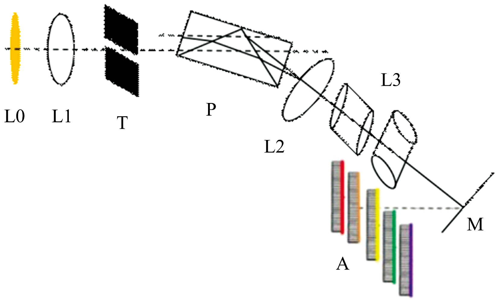
多光谱点温测量的光路系统是将待测点辐射通过物镜、 光阑、 棱镜及透镜后色散至探测器阵列。 为了实现线温测量, 在点温测量光路的基础上, 将光阑换成狭缝, 接收部分由1个探测器阵列变为多个探测器阵列, 光路图如图1所示。
 | 图1 线温测量光路 L0: 被测物体; L1: 透镜组; T: 狭缝; L2: 准直物镜1; P: 组合分光棱镜; L3: 暗箱透镜; M: 反射镜; A: 线性探测器阵列Fig.1 Line temperature light path L0: Mercury lamp; L1: Battery of lens; T: Slit; L2: Autocollimator objective; P: Combine splitting prism; L3: Camera bellows lens; M: Reflector; A: Linear detector array |
由于狭缝各点辐射除位于光轴的中心点外, 其余各点均属于离轴辐射, 因此线光源辐射通过光路系统后会出现球差(如图1, A光屏显示“ 弯曲” ), 因此不能保证分光后的线光谱辐射信息完全垂直入射至各探测器阵列, 从而影响测量精度。 为此需要对传统光路系统进行改进, 减少乃至消除球差的影响, 提高探测器接收辐射信息的能力。
1.2.1 正交透镜组光路仿真
柱状透镜具有某一个方向的汇聚作用, 为此提出在分光后的光路中, 增加2个柱状透镜, 这两个柱状透镜成正交放置, 利用第一个柱状与狭缝同方向, 进行汇聚, 第二个柱状透镜在与狭缝垂直方向进行汇聚, 可大大减少球差的影响。
利用ZEMAX软件对被测物体发射的圆盘光线经过正交柱状透镜组后, 在不同位置的成像进行仿真(图2), 形成的光线在前焦线的前方和后方的光束呈横向椭圆形, 而在后焦线的前方和后方, 光束呈纵后椭圆形。 在横焦线和纵焦线的位置, 会形成横向和纵向的聚焦线。 因此, 利用正交柱状透镜组, 可以实现不同位置呈现从竖椭圆到圆再到横椭圆再到直线的成像规律, 利用这一规律可以实现球差的校正。
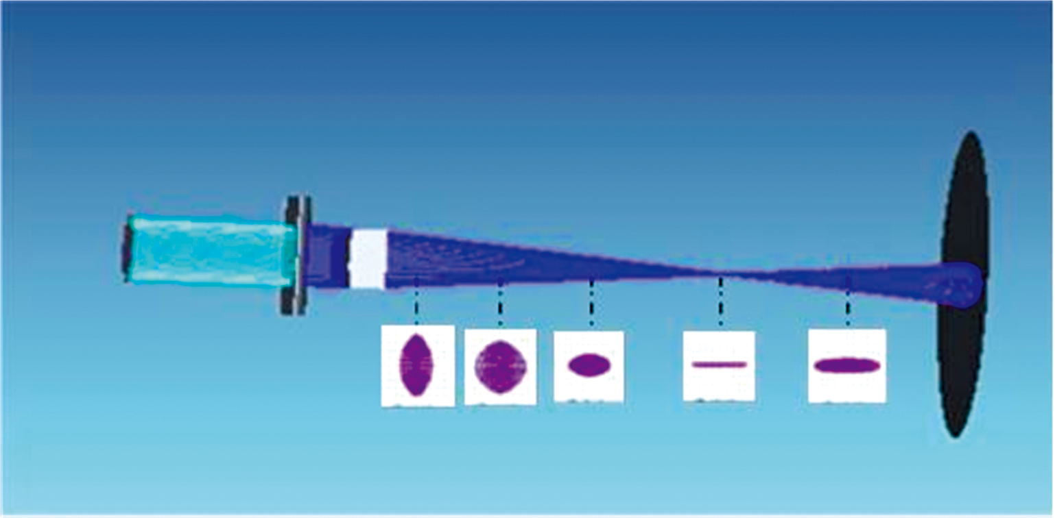 | 图2 正交柱状透镜成像示意图Fig.2 Orthogonal cylindrical lens imaging schematic diagram |
为此, 本文设计了新方案, 如图3所示, 即经狭缝后的辐射在棱镜分光后经L1、 L2透镜产生的球差, 进入一个正交柱状透镜组, 经正交柱状透镜组后弯曲光线变直, 经反射镜进入光电探测器阵列, 实现线表面辐射信息完全进入探测器, 减少远轴辐射产生的像差, 实现线温各点与探测器单元阵列的匹配, 达到测量探测器对应的各点温度的准确测量。
 | 图3 多光谱线温高温计的光路设计图 L0: 被测物体; L1: 物镜; T: 狭缝(对准待测线); P: 组合分光棱镜; L2: 透镜; L3: 正交柱状透镜组; M: 反射镜; A: 线阵探测器阵列Fig.3 Multispectral line temperature pyrometer optical circuit design drawing L0: Object; L1: Object lens; T: Slit(Align with line under test); P: Combine splitting prism; L2: Lens; L3: Orthogonal cylindrical lens group; M: Reflector; A: Linear detector array |
1.2.2 整体光路仿真
多波长辐射线温测量高温计的光学系统设计实质上是一个辐射能通道, 确保辐射温度计能准确地从被测物面所指定的面积取出辐射能量, 然后传送到硅二极管线阵各指定面元, 其主要技术要求为:
(1)在较宽的波长范围内保证成像质量, 仔细考虑消除各种有关像差。
(2)正确地取定视场光栏的口径及位置以确保在被测物面上准确地取样。
(3)正确地取定狭缝宽度及位置以确保像方光束具有指定的孔径。
(4)安排色散棱镜以便热辐射能展开成连续光谱, 注意展开光谱与探测器阵列尺寸相适配。
(5)由于所采用的S4111-16Q的硅二极管线阵每一单元的感光面积为1.45 mm× 0.9 mm。 故设计时考虑采用目标宽度为1.45 mm, 视场光栏宽度为0.73 mm, 线性放大倍数为1.0。
(6)为了满足以上的技术要求, 本文采用了S4111-16Q的16元探测器阵列, 每像元宽0.9 mm、 长4.4 mm, 中间间隔是0.1 mm, 故16元探测器阵列为15.9 mm。
经计算与设计后, 仿真的最后光学系统如图4所示。
 | 图4 光学系统仿真结果Fig.4 Optical system simulation diagram |
根据S4111-16Q的实际像元参数, 确定各个光学元器件的参数, 如表1所示。
| 表1 各个光学元器件参数 Table 1 Parameters of various optical components |
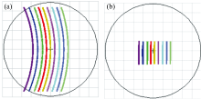
利用ZEMAX软件对有无正交柱状透镜两种情况成像结果进行对比, 如图5所示。
 | 图5 仿真光路成像结果比较 (a): 无正交透镜; (b): 有正交透镜Fig.5 Light path imaging effect picture (a): Without orthogonal lenses; (b): With orthogonal lenses |
从图5中可以看出, 在没有柱状透镜的情况下, 狭缝成像明显弯曲, 在加入正交柱状透镜的情况下, 狭缝成像弯曲现象消失, 经狭缝分光后的线光谱明显呈直线状态。
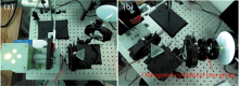
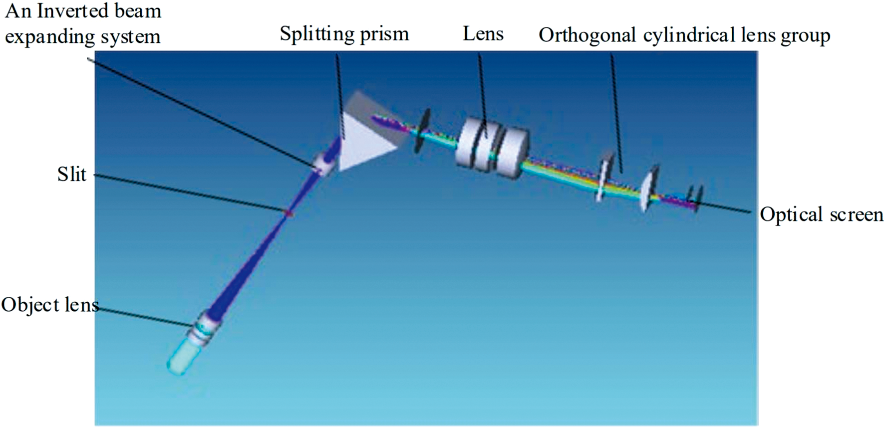
基于表1的光学系统参数所定制实际光学器件, 搭建了多光谱线温光学系统, 并进行了有无正交柱状透镜的实际对比实验, 结果如图6所示。 从图中可以明显看出, 在正交柱状透镜的作用下, 线光谱球差现象消失, 呈直线状态, 从而构建了一个完整的线温辐射通道。
 | 图6 实际光路及成像结果比较 (a): 无正交柱状透镜(狭缝成像弯曲); (b): 有正交柱状透镜(狭缝成像呈直线)Fig.6 Actual optical path system (a): No Orthogonal cylindrical lens group; (b): Orthogonal cylindrical lens group |
提出了基于正交柱状透镜的多光谱线温光路系统设计方案, 解决了线温边缘各点辐射由于离轴传输过程中的球差影响, 从而使得线光谱弯曲的问题。 经ZEMAX软件仿真后, 确定了各部分光学元器件的参数, 搭建了基于仿真参数定制的实际光学系统, 实验表明基于正交柱状透镜的多光谱线温光学系统较好地解决了球差所引入的线光谱弯曲问题, 为待测线温度辐射信息的完整采集奠定了坚实基础。
| [1] |
|
| [2] |
|
| [3] |
|
| [4] |
|
| [5] |
|
| [6] |
|
| [7] |
|
| [8] |
|
| [9] |
|
| [10] |
|
| [11] |
|
| [12] |
|
| [13] |
|
| [14] |
|