

拉曼直角反射共焦腔检测空气中二氧化碳
[黄保坤1  , 王经卓
, 王经卓1 , 宋永献1 , 朱琳1 , 张明哲2 , 欧阳顺利2, * , 吴楠楠3 ]
, 王经卓, 吴楠楠|
|


作者简介: 黄保坤, 1979年生, 江苏海洋大学电子工程学院高级工程师 e-mail: huang_baokun@163.com
拉曼光谱作为一种激发光谱, 采用激光作为激发光源, 在气体检测中可以激发所有气体分子的拉曼信号。 由于气体的分子密度低、 透光度高、 拉曼散射截面小, 导致激发光能量的利用效率低; 拉曼信号散射向四周立体空间而常规收集方法只能收集较小的空间立体角, 从而造成检测限较差而不能广泛应用于气体的检测。 提出了一种拉曼直角反射共焦腔用来提高气体等透明样品的拉曼检测的检测灵敏度。 拉曼直角反射共焦腔利用直角反射镜将入射光反射回原方向但是光路具有空间偏移的特点, 采用两个相对放置、 互相平行的直角反射镜, 将光束直径为0.7 mm的激光在工作直径为25.4 mm的共焦腔内10次来回反射, 并采用共焦点相对放置的两个透镜将激发光聚焦到焦点, 从而提高激发光能量的使用效率。 拉曼散射向激光传输方向的信号被直角反射镜反射向原方向, 经过透镜聚焦到焦点后和拉曼散射向激光入射方向的信号一起经过长通滤光片后传输向拉曼光谱仪, 从而提高了拉曼散射信号的收集效率。 以空气作为测试对象进行实验, 300 s内可以获得清晰的CO2的拉曼光谱和N2, O2的精细拉曼光谱并对其强度比进行了分析, 其中N2的2 332 cm-1, O2的1 557 cm-1, CO2的1 388 cm-1的拉曼峰的峰高比是785:257:1。 拉曼直角反射共焦腔在常规拉曼散射激发收集光路的基础上增加了两个直角反射镜和一个聚焦镜, 具有体积小, 结构简单, 易于调节的特点。 拉曼散射向周围空间的信号强度分布与入射光的入射方向有关, 在沿入射光方向及其相反方向散射信号强度最大, 拉曼直角反射共焦腔设计的收集散射信号的角度与散射信号强度分布最强方向一致, 并且利用了光学景深的优势, 最大化的提高了拉曼散射信号收集效率。 拉曼直角反射镜腔可以拓展拉曼光谱技术在气体检测中的应用, 例如用于气相化学反应的原位监控、 发动机燃烧过程及排放物检测、 未知污染物气体分析等气体成分复杂的领域。
, WANG Jing-zhuo, WU Nan-nanAs an excitation spectrum, Raman spectroscopy uses laser as an excitation source to excite Raman signals of all gas molecules. Due to the low molecular density, high transmittance of light and low Raman Scattering Cross Section, the utilization efficiency of the eycitation light energy is low, and the Raman signal scatters to space around focus, only fraction of signal can be collected by collecting system. As a result, the detection limit is poor and cannot be widely applied to the detection of gas. In this paper, a Raman right angle reflection cavity was proposed to improve the detection limit of Raman detection of transparent samples such as gases. The Raman right angle reflection cavity used a right angle mirror to reflect incident light back to the original direction but the optical path had a spatial offset. Two parallel to each other, oppositely placed right-angle mirrors were used, and the laser with a beam diameter of 0.7 mm had a working diameter of 25.4 mm. The exciting laser was reflected back and forth 10 times in the cavity, and two lenses were placed in opposite direction around focus which were used to focus the excitation light to the same focus, thereby improving the use efficiency of the exciting laser energy. The Raman scattering signal transmitted along with the direction of incident laser was reflected back by the right-angle mirror to the right about, after being focused by the lens to the focus, with the Raman scattering signal scattered to the laser incident direction all passes through the long-pass filter and collected by Raman spectrometer, thereby improving the collection efficiency of Raman scattering signals. The experiment was carried out with air as the test object. The Raman spectrum of clear carbon dioxide and the fine Raman spectrum of nitrogen and oxygen were obtained within 300 s and the intensity ratio was analyzed, including 2 332 cm-1 of nitrogen and 1 557 cm-1 of oxygen. The peak height ratio of the 1 388 cm-1 Raman peak of carbon dioxide was 785:257:1. The Raman right angle reflection cavity added two right-angle mirrors and one focusing mirror compare to the conventional Raman scattering excitation collecting system, and had the characteristics of small volume, simple structure and easy adjustment. The signal intensity distribution of Raman scattering to the surrounding space was related to the incident direction of the incident light, and the maximum of Raman signal accorded with the direction of the incident light and the reverse direction. The Raman right angle reflection cavity was designed to match the Raman signal intensity distribution, and along with the advantages of optical depth of field was utilized to maximize the Raman scattering signal collection efficiency. The Raman right-angle mirror cavity can extend the application of Raman spectroscopy in gas detection, such as in-situ monitoring of gas phase chemical reactions, engine combustion processes and emissions detection, and unknown pollutant gas analysis.
拉曼光谱采用激光作为激发光源, 激发分子的振动、 转动能级发生跃迁, 并根据散射光与入射光的能量差确定不同分子的振动、 转动能级, 从而对分子种类进行准确的定性分析, 被称为分子指纹谱。
当拉曼光谱应用于气体检测时, 激光可以激发几乎所有气体分子的拉曼光谱, 因此适用于除惰性气体外几乎所有气体分子的检测, 不受限于气体分子的种类和大小。 而且由于气体分子处于布朗运动状态, 受周围环境的影响较小, 分子性质均一, 使得气体分子的拉曼峰的半高宽较窄, 又由于气体分子一般为小型分子, 所以气体分子的拉曼峰数量少, 使得拉曼光谱技术适合对气体分子, 尤其是对组成复杂的多种成分气体分子进行分析[1]。
气体对于激光具有良好的透过性, 这种现象既有其优点, 又有其缺点。 其优点在于, 气体分子被激发出来的拉曼散射信号在传输过程中被吸收而损失的比例非常少, 以至于可以忽略不计, 所以拉曼光谱强度只和气体分子的拉曼散射截面和分子数量有关, 有采用朗伯比尔定律根据拉曼光谱强度对气体分子进行定量分析[2]。 其缺点在于, 采集拉曼光谱信号时, 由于拉曼光谱是散射信号的特性和光谱仪采用狭缝作为入光孔的特点, 造成只能采集一个较小范围的空间点。 气体的拉曼散射截面只有10-30 cm2· sr-1 [3], 而且空气中气体分子密度较低, 造成拉曼用作气体检测时检出限较差而无法广泛应用。
为了在常温常压下, 在常规拉曼光谱仪上提高对气体的检测限, 主要方法是提高激发光源能量的使用效率, 其中包括: 近共焦腔(near-confocal cavity)[1, 4, 5], 逆向多重反射池(retroreflecting multi pass cell)[6, 7], 多通道拉曼增益池(multi-pass Raman gain cell)[8], 能量聚集腔(power build up cavity)[9], 改进型多通道拉曼光谱仪(improved multiple-pass Raman spectrometer)[10], 共焦腔增强[11]等, 以上方法的基本原理是采用凹面反射镜或者直角反射镜使激光多次聚焦到样品点, 充分利用激发光的能量, 提高拉曼光谱强度, 在垂直激发光路方向放置凹面反射镜和收集透镜, 凹面反射镜将拉曼散射信号反射回焦点后传输向收集透镜从而提高收集效率。 这些装置至少需要4组光具组来实现, 两组光学元件来实现激光在腔里的振荡, 第三组光学元件收集拉曼散射信号并将其变成平行光传输向光谱仪, 第四组光学元件与第三组光学元件沿聚焦点对称放置, 通常是凹面反射镜将散射的拉曼信号重新聚焦到焦点, 然后传输向第三组光学元件并最终传输向光谱仪。
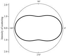
由于散射光的强度与激发光入射方向有关, 以垂直于光入射方向的散射强度为1作为标准, 那么散射光强度与角度的关系为式(1), 散射光强度分布如图1。
这种情况下平行于入射光的散射光强度为垂直方向的2倍, 所以从平行于入射光方向进行收集效果较好。
 | 图1 拉曼散射强度分布示意图Fig.1 Raman scattering intensity distribution diagram. 0 degree is the direction of laser incident |
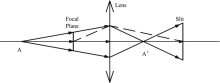
考虑拉曼信号收集透镜景深的影响, 位于收集透镜光轴上, 但是在焦点外的拉曼散射信号也具有一定的几率被收集进拉曼光谱仪, 如图2。 所以当激发光传输方向与收集透镜光轴重合的时候, 才能最大效率的利用激发光的能量。 又因为激光光束属于高斯光束, 在中心的激光能量最强, 进一步增加了激光的使用效率。
 | 图2 景深对于拉曼散射信号收集效率的影响 其中狭缝是焦点通过收集透镜的成像, 焦点外位于光轴上的A点, 通过收集透镜成像到A’ 点, A点发出的拉曼散射信号经过焦点的仍然可以通过狭缝进入光谱仪Fig.2 Influence of depth of field on Raman scattering signal collection efficiency Where the slit is the focal plane through the collection lens, the focus is located at point A on the optical axis, and is imaged by the collecting lens to the point A’ ; The Raman scattering signal from point A passes through the slit and can still enter the spectrometer through the slit |
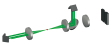
拉曼直角反射共焦腔如图3所示, 与传统的拉曼散射信号收集方式相比, 增加了2个直角反射镜和1个透镜。
 | 图3 拉曼直角反射共焦腔中激发光路示意图Fig.3 The schematic diagram of exciting light transfer in right angle mirror cell of Raman |
激光通过直角反射镜1的通光孔之后, 由长通滤光片反射向聚焦镜1, 由聚焦镜1聚焦到焦点的气体上, 穿过焦点后发散的激光由聚焦镜2准直为平行光, 到达直角反射镜2后由直角反射镜2在空间偏移一定的距离之后传输向激光入射方向的逆方向。 到达直角反射镜1之后再次空间偏移并沿激光传输方向传输向焦点。 因为激光光斑直径小于1 mm, 而使用的透镜的直径是25.4 mm, 所以经过直角反射镜1和直角反射镜2调制之后激光可以10次聚焦到焦点。
拉曼信号传输方式如图4所示, 由焦点的气体发出的拉曼散射信号散射向立体空间并且最大强度在沿激光传输方向, 传输向聚焦镜2的拉曼散射信号会被聚焦镜2和直角反射镜2反射回焦点, 然后和散射向聚焦镜1的拉曼散射信号一起经过长通滤光片传输向拉曼光谱仪。
实验采用的光谱仪是Andor公司的SR500, 试验状态狭缝宽度100 μ m, 检测器是Andor公司的DU920P-BU型号CCD, 激光器是Cobolt公司的532 nm激光器, 输出功率50 mW, 激光光斑直径为0.7 mm。
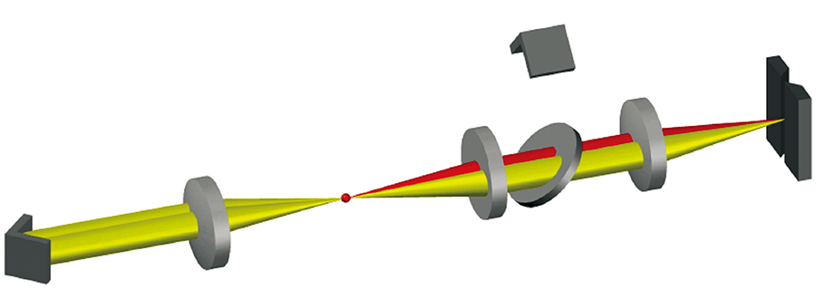 | 图4 拉曼直角反射共焦腔中散射信号的传输方式Fig.4 The schematic diagram of scattering light transfer in right angle mirror cell of Raman |
拉曼直角反射共焦腔用于测试实验室中空气的拉曼光谱, 在保持实验室通风状态良好的情况下曝光300 s测得空气的拉曼光谱如图5。 其中N2的2 332 cm-1, O2的1 557 cm-1, CO2的1 388 cm-1的拉曼峰的峰高比是785:257:1。
 | 图5 空气的拉曼光谱图 (a): 放大后的SO2的拉曼光谱图; (b): 局部放大后的O2的拉曼光谱图; (c): 局部放大后的N2的拉曼光谱图Fig.5 Raman spectrum of air (a): Partially enlarged view of CO2; (b): Partially enlarged view of O2; (c): Partially enlarged view of N2 |
本文的拉曼直角反射镜腔, 使用较少的光学元件, 较低的激光功率情况下, 以空气为测量对象, 获得了空气中O2, N2和CO2的的拉曼信号, 并对其强度比进行了分析。 为拉曼测试气体提供了一种新的简单、 有效的方法。
| [1] |
|
| [2] |
|
| [3] |
|
| [4] |
|
| [5] |
|
| [6] |
|
| [7] |
|
| [8] |
|
| [9] |
|
| [10] |
|
| [11] |
|