


两种荧光粉混合涂覆的白光LED的光谱方程的建立
[许建文1, 2  , 陈国庆
, 陈国庆1, 2, * , 吴亚敏1, 2 , 马超群1, 2 , 辜姣1, 2 ]
, 陈国庆, 吴亚敏|
|


作者简介: 许建文, 1993年生, 江南大学理学院硕士研究生 e-mail: 1757762435@qq.com
为了有效地模拟两种荧光粉混合涂覆的白光LED的发光光谱, 选用了硅酸盐系列的绿色荧光粉与高显粉系列的红色荧光粉, 应用英国Edinburgh FLS920P型荧光光谱仪, 对绿色荧光粉与红色荧光粉进行荧光光谱的实验测量, 得到绿色荧光粉发射峰在527 nm, 红色荧光粉发射峰在641 nm。 配置浓度为7%~17%, 比例为3∶1~3∶2的样本, 共144个, 应用杭州远方色谱有限公司的HAAS-2000高精度光谱辐射计测量LED发光光谱, 最后处理数据, 得到拟合函数, 在这些函数的基础上构建出了光谱方程, 该光谱方程是模拟两种荧光粉的浓度和比例的系统方法。 为了较为准确的预测出两种荧光粉混合后涂覆于蓝光芯片的发光光谱, 对于实验中的数据进行了三维曲面拟合, 得出荧光粉的浓度与比例和绿修正系数与红修正系数之间的函数关系式。 将得出的绿修正系数和红修正系数的函数关系式应用到光谱方程中, 得出最终模拟白光LED发光光谱的一种新方法。 并且用了两组的模拟光谱图与实验的光谱图进行对比, 发现两种光谱图的吻合效果都较为良好。 说明这种模拟白光LED的新方法确实可行, 且预测的两种荧光粉混合后涂覆于蓝光芯片的发光光谱较为准确。 该方法将具体的荧光粉的质量比和浓度与LED的发光光谱图联系了起来, 而之前的大多数研究都是将光谱功率分布与LED发光光谱图联系起来, 并未涉及到荧光粉的质量比与浓度。 在建立了具体的光谱方程之后, 可以在没有实验仪器和不做实验的情况下, 根据两种荧光粉的质量比, 以及与AB胶混合后的浓度直接得出最终的模拟白光光谱, 可以摆脱实验仪器以及其他因素的限制。 并且为制备具有特定光谱特性的白光LED提供了新思路, 具有一定的实用价值。
In order to effectively simulate the luminescence spectrum of two kinds of phosphor mixed coated white LEDs, the silicate series of green phosphors and high-viscosity series of red phosphors were selected. Fluorescence spectra of green phosphors and red phosphors were measured by the British FLS920P fluorescence spectrometer. The emission peak of green phosphor was 527 nm and the emission peak of red phosphor was 641 nm. Totally, there were 144 samples, which have a concentration ranging from 7% to 17% and a proportion of 3∶1 to 3∶2. The HAAS-2000 high-precision spectroradiometer from Hangzhou Yuanfang Spectrum Co., Ltd. was used to measure the LED luminescence spectrum. Finally, the data were processed to obtain the fitting function. Based on these functions, the spectral equation was constructed. This spectral equation is a systematic method of simulating the concentration and proportion of two phosphors. In order to accurately predict the luminescence spectrum of the two kinds of phosphors mixed and applied to the blue chip, a three-dimensional surface fitting was performed on the data in the experiment, and the relationship between the concentration and proportion of the phosphor and the green correction coefficient and the red correction coefficient was obtained. Applying the obtained functional relationship between the green correction coefficient and the red correction coefficient to the spectral equation, a new method for finally simulating the luminescence spectrum of white LEDs was obtained. Moreover, the simulated spectra of the two groups were compared with the actual experimental spectra, and the results of the two spectra were found to be good. This new method of simulating white LEDs is indeed feasible, and the predicted phosphorescence spectra of the two phosphors coated on the blue chip are more accurate. This method relates the specific phosphor mass ratio and concentration to the luminescence spectrum of the LED, and most previous studies have linked the spectral power distribution to the LED luminescence spectrum, the mass ratio and concentration of the phosphor are not involved, and the specific breakthrough is compared. After the specific spectral equation is established, the final simulated white light spectrum can be directly obtained according to the mass proportion of the two phosphors and the concentration after mixed with the AB glue without the experimental instrument and without the actual experiment. Get rid of the limitations of experimental instruments and other factors. And it provides a new idea for the preparation of white LED with specific spectral characteristics, which has certain practical value.
随着白光LED行业的迅速发展, 人们对白光LED的发光性能提出了越来越高的要求, 如更高的发光效率、 更高的显色指数以及适合于各种不同照明条件的色温等[1]。 白光LED灯与普通照明用普通白炽灯和荧光灯相比, 具有使用寿命长、 可靠性高、 环保、 功耗低、 体积小等优点[2, 3, 4]。 白光LED可以由蓝光芯片和黄色荧光粉(或者是绿色荧光粉和红色荧光粉)实现[5]; 也可以是紫外芯片与蓝色荧光粉、 红色荧光粉、 绿色荧光粉混合所得[6], 这种方法以其低成本和高发光效率而闻名[7]。 而如今使用最为广泛的且成本较低的方法是用宽带绿色荧光粉与InGaN蓝光芯片或GaN蓝光芯片组合, 但是往往这种组合的显色指数都低于80, 而室内照明的显色指数都要高于80, 所以用加入红色荧光粉来提高显色指数, 可以很好的解决这一问题[8]。
为了更准确的对光谱进行预测, 近年来对多荧光粉构成的白光LED的光谱优化已然成为了研究热点[8]。 本文采用在蓝光LED芯片上涂覆绿、 红荧光粉的方法来实现白光LED, 且制备了大量不同浓度和比例的样品, 并最终实现了在已知实际荧光粉质量比与浓度的情况下就能得出目标光谱图, 并与实验光谱图吻合效果良好。
杭州萤鹤光电材料有限公司硅酸盐系列的YH-S525M绿色荧光粉; 高显粉系列的YH-C640E红色荧光粉; 道康宁公司的A胶与B胶; GaN蓝光LED芯片。 杭州远方色谱有限公司带有夹具的积分球的HAAS-2000高精度快速光谱辐射计; 英国Edinburgh FLS920P型荧光光谱仪。
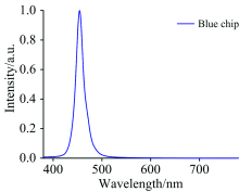
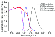
使用高精度快速光谱辐射计测量了蓝光LED芯片的发光光谱(图1), 发射峰位置在455 nm。 使用荧光光谱仪测量红色荧光粉与绿色荧光粉的激发与发射光谱(图2), 图2中绿色荧光粉的发射峰位置在527 nm, 红色荧光粉的发射峰位置在641 nm。
 | 图1 发射峰在455 nm的蓝光LED光谱Fig.1 Blue LED spectra with wavelength 455 nm |
 | 图2 两种荧光粉的激发光谱与发射光谱Fig.2 Excitation and emission spectra of two phosphors |
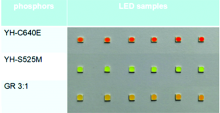
将荧光粉与AB胶混合, 搅拌均匀后涂覆于带凹槽的蓝光LED芯片上, 然后放在150 ℃的烘烤箱里固化1.5 h, 将固化后的样品冷却至室温后, 使用带有夹具的积分球测量其发光光谱。
 | 图3 不同荧光粉涂覆的LED样品Fig.3 LED samples with different phosphors |
优化光谱的主要影响因素是不同浓度和比例的两种荧光粉的吸收和发射的相互作用。 浓度是指荧光粉的质量与荧光粉和AB胶总质量的比值。 比例是指两种荧光粉的质量比。 这一过程可以被分解为一系列的光谱方程[9], 他们可以被写成
其中, yrr和ygr是红色荧光粉和绿色荧光粉占总荧光粉的比例。
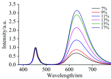
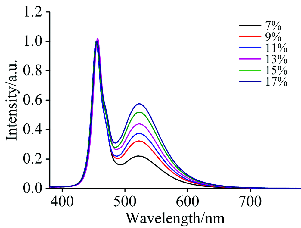
光谱方程的获得分为3步, 第一步是测量单一荧光粉随浓度增加的光谱。 考虑到荧光粉的封装以及色温的影响, 选择的浓度范围是7%~17%。 单一的红色荧光粉和单一的绿色荧光粉浓度从7%增加到17%(浓度间隔为2%)的总光谱都归一化到蓝光峰, 如图4和图5所示。
 | 图4 归一化到蓝光峰的红色荧光粉总光谱Fig.4 Total spectra of red phosphor with normalized to their blue peaks |
 | 图5 归一化到蓝光峰的绿色荧光粉总光谱Fig.5 Total spectra of green phosphor with normalized to their blue peaks |
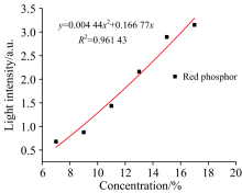
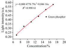
然后记录下归一化后的峰值强度值。 对归一化到蓝光峰之后的绿、 红峰值进行曲线拟合, 结果如图6和图7所示。
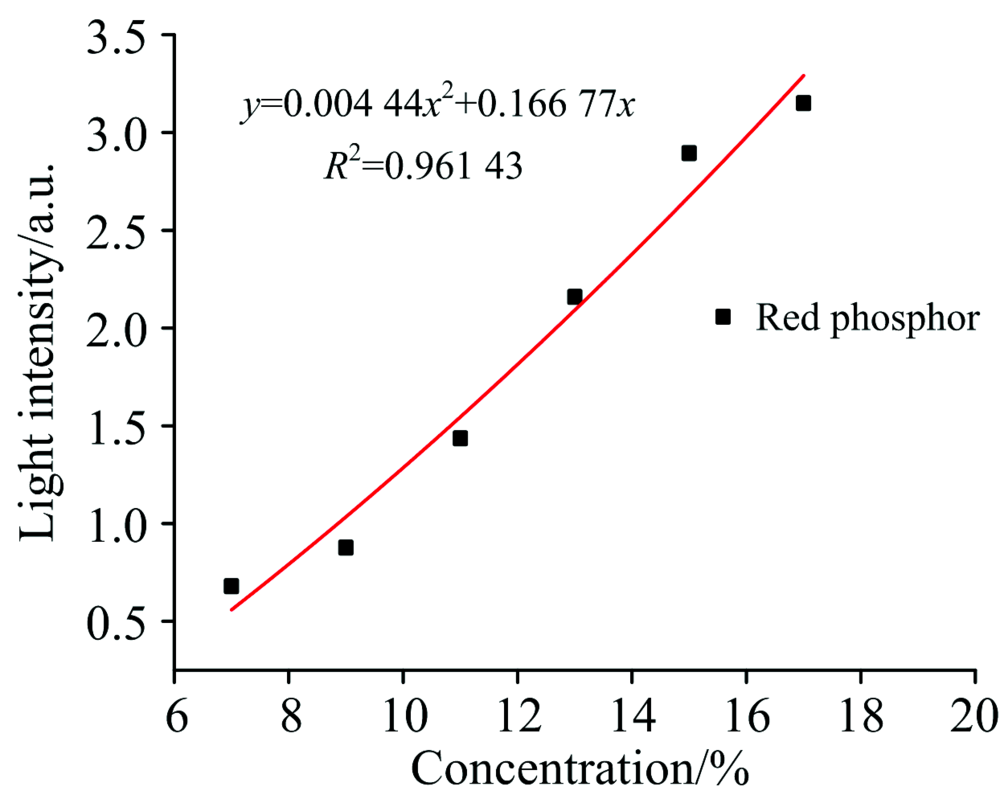 | 图6 不同浓度红色荧光粉的光强度Fig.6 Light intensity of different concentration red phosphor |
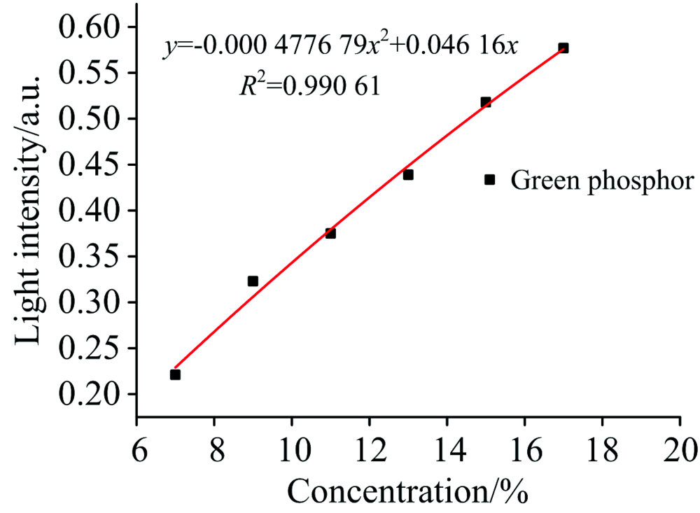 | 图7 不同浓度绿色荧光粉的光强度Fig.7 Light intensity of different concentration green phosphor |
因此, 单一荧光粉的光强与浓度的经验公式可表示为
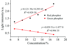
第二步是测量两种恒定比例的荧光粉随浓度增加的吸收和发射相互作用的光谱。 考虑到显色性要较高, 实验中使得绿色荧光粉和红色荧光粉的恒定比例为3∶ 1[10]。 同样, 在恒定绿色荧光粉和红色荧光粉比例为3∶ 1的情况下, 荧光粉的浓度也是从7%增加17%, 并将测得的光谱归一化到蓝光峰, 如图8所示。 并记录归一化到蓝光峰后的绿峰值和红峰值。
 | 图8 绿色荧光粉和红色荧光粉恒定比例下不同浓度的总光谱Fig.8 Total spectra of constant proportion of green and red phosphors with different concentrations |
绿色荧光粉与红色荧光粉相互作用的经验公式如式(5)和式(6)
 | 图9 绿色和红色荧光粉恒定比例下不同浓度的光强度Fig.9 Light intensity of constant proportion of green and red phosphors with different concentrations |
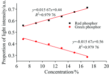
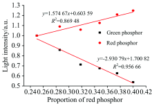
在图10中, 绿色荧光粉和红色荧光粉在不同浓度下光强比例的经验公式可表述如式(7)和式(8)
 | 图10 不同浓度的绿色和红色荧光粉的光强度比例Fig.10 Proportion of light intensity of green and red phosphors with different concentrations |
第三步是测量红色荧光粉比例不断增加且在不同浓度下的光谱。 并记录了红色荧光粉比例不断增加且在不同浓度下的光谱归一化到绿色荧光粉和红色荧光粉比例为3∶ 1的绿光峰和红光峰之后的峰值强度。
图11显示了不同浓度和比例的平均归一化峰值。 因此, 不同比例荧光粉光谱归一化到绿色荧光粉和红色荧光粉比例为3∶ 1的绿光峰和红光峰之后的经验方程可表述如式(9)和式(10)
 | 图11 不同浓度比例的平均光强度Fig.11 Average light intensity of proportions among different concentrations |
参考文献中的模拟白光光谱=归一化的蓝光LED芯片发光光谱+归一化的绿荧光粉发射光谱× yg+归一化的红荧光粉发射光谱× yr。
由于不同的荧光粉的原料组成以及各方面的光学性质都有区别, 所以该光谱方程需要加以完善才能符合我们选用的这两种荧光粉。 于是对于实验光谱图中的绿峰值与红峰值取值并记录。 将这些实验绿峰值和红峰值分别与用参考文献中的模拟白光光谱的方法得出的光谱图中的绿峰值和红峰值做比值。 然后将这些数据用MATLAB的三维曲面拟合, 得出绿修正系数和红修正系数的方程。 绿光的修正系数方程和红光的修正系数可表述如式(11)和式(12)
fg(x, y)=-17.05-45.5x+15.12y+55.37x2-8.844xy-1.153y2-23.86x3+4.085x2y-0.020 13xy2+0.068 92y3+3.378x4-0.572x3y-0.011 47x2y2+0.002 22xy3-0.001 58y4(11)
fr(x, y)=-70.32+30.29x+20.08y+15.45x2-13.83xy-1.36y2-14.91x3+5.814x2y+0.110 6xy2+0.072 26y3+2.719x4-0.811 4x3y-0.020 32x2y2-0.000 525 5xy3-0.001 506y4(12)
式(11)和式(12)中的x和y分别代表绿红荧光粉的质量比与浓度值。
最终模拟的白光光谱=归一化的蓝光LED芯片发光光谱+归一化的绿荧光粉发射光谱× yg/fg(x, y)+归一化的红荧光粉发射光谱× yr/fr(x, y)。
图12是光谱方程建立中未用到的浓度与比例的样品的实验光谱图与模拟光谱图, 用以检验光谱方程的准确性。 由于模拟光谱图中的绿光和红光部分用的是由荧光光谱仪测得的绿色荧光粉和红色荧光粉的发射谱, 而实验中荧光粉混合后涂抹于LED芯片上的光谱图是由高精度快速光谱辐射计测得, 所以模拟图与实验图对比, 模拟图中的绿光和红光部分较实验图中的绿光和红光部分有点向长波长方向偏移, 这是由于两种仪器测出来的绿光峰和红光峰存在几纳米的差别所造成的。 总的来说, 模拟的LED光谱图与实验的LED光谱图有较高的吻合度。 说明建立的光谱方程能较为准确的模拟出白光LED的光谱图。
 | 图12 模拟光谱图与实验光谱图Fig.12 Simulated spectrum and experimental spectrum |
建立的光谱方程能较为准确的模拟出白光LED的光谱图, 且在建立了具体的光谱方程之后, 可以在没有实验仪器和不做实际实验的情况下, 根据两种荧光粉的质量比, 以及与AB胶混合后的浓度直接得出最终的模拟白光光谱, 并且这种方法得出的光谱与实际的实验光谱吻合度较高。 为制备具有特定光谱特性的白光LED提供了一种新的思路。 同时也对于后续根据模拟出的光谱对白光LED的色坐标、 色温、 及显色指数及其他LED参数和指标的研究具有一定的参考价值。
| [1] |
|
| [2] |
|
| [3] |
|
| [4] |
|
| [5] |
|
| [6] |
|
| [7] |
|
| [8] |
|
| [9] |
|
| [10] |
|