


分体式原向反射法水下武器速度测试技术研究
[刘吉1, 2  , 武锦辉
, 武锦辉1 , 于丽霞2 , 张静2 , 杨琦2 ]
, 武锦辉|
|


作者简介: 刘 吉, 1980年生, 中北大学信息与通信工程学院副教授 e-mail: 275952794@qq.com
水下动态参数的测试是特种武器、 两栖武器、 水下专用武器性能考核的必备环节, 而水下运动体的速度信息是评价水下武器性能的重要指标之一。 针对现有的水下高速目标参数测试系统中存在的成本高、 安装调试复杂、 设备体积庞大等问题, 提出一种以激光光幕为有效区域水上、 水下分体式, 实时、 非接触的测速方法。 通过分析Lambert-Beer定律和体散射函数等数学原理, 确定了水下光谱传输规律综合考虑性价比获得最佳峰值波长; 将1m的圆柱体作为散射体模拟光在水中的散射情况, 追迹空间区域内的光线总数为1×10⁵, 获得位于传播方向上1, 3, 5和7 m处的接收面上辐照度的光能量分布, 从而获取系统激光光源的最佳峰值功率。 以此为依据, 采用定距测时原理和一维原向反射技术, 由峰值波长为532 nm的半导体光纤耦合绿光激光器、 光纤耦合式鲍威尔棱镜防水扩束器、 一维原向反射器等构建光学系统。 激光光源、 光电转换部分和信号调理部分位于水上, 激光光幕和原向反射器位于水下, 通过光纤束完成两路光信号的发射和反射光的回收。 发射端光纤一端与光源耦合, 另外一端与鲍威尔棱镜耦合置于水下形成扇形光幕。 接收端光纤一端均布于鲍威尔棱镜出口, 另一端与PIN型光电传感器耦合。 设计齿形一维原向反射器并完成加工制造, 光线将沿着入射光方向原向返回, 另外一维方向则仍为镜面反射, 将接收系统置于发射点垂直光面内附近即可接收大部分光能量, 解决了现有原向发射器因水介质折射率不同于空气而导致原向反射特性消失的问题。 实验采用波长为(532±5) nm绿光激光器, 功率稳定性<1%, 光学噪声< 0.5%, 准直后耦合至长度为2 m的单模光纤再经过鲍威尔棱镜展宽为60°扇形一字线光幕, 扩束模块封装采用尼龙防水材料, 接收光纤均布于光源周围形成环形光纤束, 光纤另外一端均匀排列与PIN光敏二极管直接耦合。 光敏二极管前加中心波长为532 nm的光学滤光片, FWHM=(3±1) nm, 透过率为70%。 PIN型光敏二极管有效尺寸为5.0 mm×5.0 mm。 采用多档可调的光电信号调理电路以适应不同尺寸的测试对象。 该系统进行了不同目标速度参数测试实验, 以钢弩为发射装置, 信号经过光纤回收、 信号调理, 采集至计算机处理获得波形及区间内平均速度, 两激光光幕之间的距离为定值300 mm, 波形峰值作为计时时刻。 成功获取了较高信噪比的波形信号和目标速度值。 利用水下运动体模型与模拟结果进行比较得到其绝对误差。 实验结果表明: 本方法结构简单、 重复性好, 可实现有效区域达到1 m×1 m, 最小可测目标尺寸为5 mm, 理论测速上限可达1 000 m·s-1, 实验数据通过与理论经验公式结果比对表明, 系统测试精度可达0.2%。
Dynamic parameter measurement is the essential of performance for special weapons, such as amphibious and underwater special weapons. The information about velocity of moving target underwater is one of the important factors for evaluating underwater weapons performance. There are many disadvantages of the traditional connect measurement method, for example, aluminum foil target and comb target have poor reliability, small effective area and low repeatability in an underwater environment. At the same time, the methods of Doppler and sonar are very expensive. In order to solve these problems, we propose a real-time and non-contact method to obtain weapon velocity parameters based on the split-type reflective and with laser screen as effective area. The law of underwater spectral transmission is determined by analyzing the law of Lambert-Beer and the function of body scattering and other mathematical principles. The optimal laser peak wavelength was obtained. A 1 m-diameter cylinder was created as a scatterer to simulate the scattering of in water. The total number of traced space rays was 1×10⁵. And the light energy of the irradiance at the receiving surface located at 1, 3, 5, and 7 m was obtained. So the optimal peak power of the system laser source was obtained also. On the basis of this, the optical system adopted principle of determining the distance measuring time principle and the one-dimensional retro-reflective technology, which consisted of 532 nm, fiber-coupled semiconductor lase,fiber-coupled laser beam expander used Powell lens and retro-reflector. The laser emission part and the signal processing part were located on the water, and the effective area of the laser screen was located under the water. The laser was emitted and the signal was recovered by the optical fiber. One end of the transmitting optical fiber was coupled with the light source, and the other end of the optical fiber was coupled with the Powell lens to form a fan-shaped light screen under water. One end of the receiving optical fiber was distributed at Powell prism exit, and the other end was coupled with the PIN-type photoelectric sensor. One-dimensional tooth-shaped retro-reflector was designed and manufactured, the light would be returned along the original direction, and the other dimensional direction would observe the principle of specular reflection. The receiving system was placed near the vertical point of the emission point in order to collect most of the reflected light. The problem of the current reflector was solved, that is to say, reflection characteristic disappeared, because the refractive index of the water was different from the air. The experiment adopted a laser with a wavelength of (532±5) nm, power stability <1%, optical noise <0.5%. After it was collimated, the laser was coupled to a single-mode fiber with a length of 2 m, then was widened to a 60° fan sharp laser screen by a Powell lens. The beam expander module used nylon as the waterproof material, and the receiving optical fiber was uniformly distributed around the light source to form an annular fiber bundle, and the other end of the optical fiber was evenly arranged and directly coupled with the PIN photodiode. In front of the photodiode, a center wavelength 532 nm optical filter was added, FWHM = (3±1) nm and the transmittance was 70%. The effective size of the PIN photodiode was 5.0 mm×5.0 mm. Adopted multiple adjustable optical signal conditioning circuits to adapt to different sizes of targets. The system performed different velocity of targets measurement. The steel file was used as a launching device. The signal was collected through fiber; then processed by conditioning circuit, finally, transmitted to the computer. The waveform and the average velocity were obtained. The distance between the two laser screens was a constant value of 300 mm, and the peak value of the waveform was used as a timing moment. The higher SNR waveform signals were acquired successfully. That system has been tested for different target speed parameters, and the waveform signal and the target speed value of higher signal-to-noise ratio have been successfully obtained. The experiments of different target were set up, and the signal waveform with high signal-to-noise ratio was successfully obtained. The absolute error was obtained by comparing the underwater moving target model with the simulation results. The experimental results showed that the proposed method can achieve the test requirements of 1 m×1 m in effective area, the minimum measurable target size of 5 mm. The accuracy of system was more than 0.2%, though compared with the results of initial velocity measurement and empirical formula.
水下枪械的速度参数测试一直是武器研发、 生产、 校验等过程中必要的环节, 测量弹丸的速度可验证武器的弹道模型和制造质量[1]。 由于介质不同, 空气中的弹道规律不再适用于水下环境, 而是呈现出弹道弯曲、 快速衰减等特征[2, 3, 4]。
GPS测速法由于水下电磁信号的屏蔽作用, 也无法使用[5, 6]。 相机成像法广泛应用于材料性能测试、 高速目标速度和坐标测试等领域[7, 8], 但是高速成像方法应用于水下环境, 需要考虑水下防护和背景照明等因素, 导致系统复杂成本提高。 采用光幕构建有效区域的定距测速法以实时、 非接触、 高精度等优点成为速度测试的主流手段[9, 10]。 如天幕靶和激光靶, 将激光光幕法应用于水下武器速度测试具有广阔的应用前景[11]。 本文在分析水下环境中光的传输、 吸收、 散射等理论的基础上, 提出一种光纤束传输水上、 水下分体, 水下采用一维原向反射激光光幕的弹丸测速方法, 可望解决目前水下弹丸速度测试中的问题。
光在水中传输时, 由于水体的吸收和散射效应造成光能量和传输方向发生改变。 吸收会造成光能量的损耗, 而散射则会改变光的传输方向。 根据Lambert-Beer定律, 光在水中传输时以指数形式衰减[12, 13]。 假设水体是均匀的, 光在水中的传输函数可表示为
式(1)中, cλ 为水中的衰减系数, d(x)为光的传输距离, λ 为光波长。 衰减是由吸收和散射共同作用的结果。 假设水体为各向同性介质, 衰减系数cλ 可表示为吸收系数aλ 和散射系数bλ 之和, 即cλ =aλ +bλ 。 散射系数bλ 表示散射点上所有
散射角上发生的散射总和, 可表示为体散射函数β λ (θ )的积分
式(2)中, cλ , aλ , bλ 和β λ (θ )都是水介质的固有参数。
为了分析在有效光幕区域内系统最佳参数, 设定一直径1 m的圆柱体作为散射体来模拟光在水中的散射情况。 设置圆柱体的材料属性表征水中粒子浓度、 尺寸及折射率等参数来模拟自然水体的效果。 设追迹光线总数为1× 10⁵, 为便于观察只显示其中100条, 模拟结果如图1所示。 当光源功率为0.5 W时, 位于传播方向上1, 3, 5和7 m处的接收面上辐照度分布显示曲线如图2所示。
 | 图1 水下光散射追迹图Fig.1 The tracing of scattered ray in water |
 | 图2 不同距离接收面辐照度分布图Fig.2 The illumination on the receiver with different distance |
根据激光辅助照明技术及原向反射技术等现有的研究基础, 结合实际测试过程中对成本、 精度、 安装调试复杂度的要求及测试环境恶劣等因素的影响, 设计光纤束传输的激光光幕和光能量回收分体非接触式水下高速目标动态参数测试系统。 将测试系统分为水上和水下两个部分, 如图3所示, 水下部分为光纤耦合的激光光幕构成探测区域部分, 当有目标通过触发光幕时, 光电探测器上接收到的光通量会发生变化, 产生光信号, 经光电探测器光电转换后形成微弱的电流信号, 由后级硬件电路对其进行信号处理。 水上为光源、 光电信号转换、 信号整形和解调及上位机部分。
 | 图3 测试系统组成原理图Fig.3 The schematic of measurement system |
目前的光原向反射材料主要应用于空气中, 且反射效率不高, 现有的产品不能满足针对水下环境的特殊需求, 设计锯齿形反射器阵列作为一维原向反射屏来回收光幕光能量, 光线将沿着入射光原向返回, 而另外一维方向则为镜面反射, 只需将接收系统置于发射点垂直光面内附近即可接收大部分光源能量。 该反射器在光幕共面方向, 光路如图4所示, 其3D模型如图5所示。
 | 图4 一维原向反射器原理图Fig.4 The theory of 1D original reflection |
 | 图5 一维原向反射器的3D模型Fig.5 3D model of original reflection |
根据前述光学系统原理, 采用波长为(532± 5) nm绿光激光器, 功率稳定性< 1%, 光学噪声< 0.5%, 准直后耦合至长度为2 m的单模光纤再经过鲍威尔棱镜展宽为60° 扇形一字线光幕, 激光展宽模块封装采用尼龙作为防水材料, 光纤接口处采用特殊的防水胶, 如图6所示。 依据原向反射原理, 反射光返回至光出口处, 接收光纤均布于光源周围形成环形光纤束, 光纤另外一端均匀排列与PIN光敏二极管直接耦合。 光敏二极管前加光学滤光片, 其中心波长532 nm, FWHM=(3± 1) nm, 透过率为70%。 PIN型光敏二极管有效尺寸为5.0 mm× 5.0 mm。 采用多档可调的光电信号调理电路以适应不同尺寸的测试对象, 水槽布置方式如图7所示。
 | 图6 激光整形发射模块图Fig.6 The module of laser emission |
 | 图7 实验现场布图Fig.7 Experimental setup |
测试目标为5 mm钢珠, 以钢弩为发射装置, 信号经过光纤回收、 信号调理, 采集至计算机处理获得波形及区间内平均速度, 典型波形如图8所示。 为了求出模拟目标的速度, 使用经典的速度计算公式v'=s/t进行求解, s是两激光器之间的距离为定值300 mm, t为两过靶信号最高点间的时间差, 波形峰值作为计时时刻。
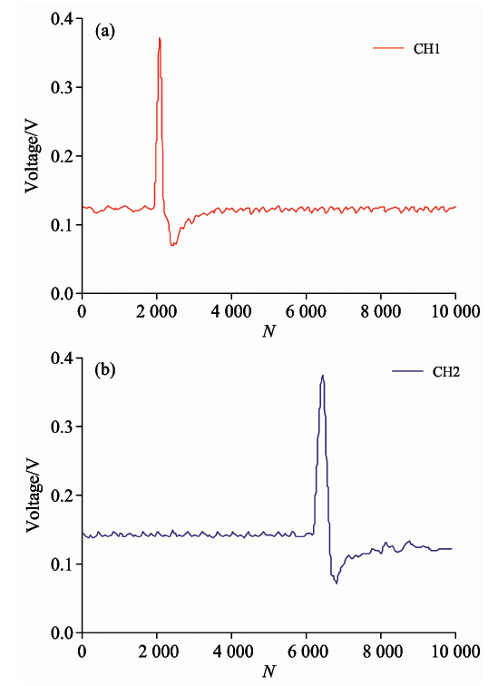 | 图8 目标波形图Fig.8 The waveform of target |
利用水下运动体模型v=v0
| 表1 实验数据表 Table 1 Experimental data |
为实现水下高速目标速度参数的测试, 根据定距测时基本原理和水下光传输理论, 结合有效区域与产品性价比等因素, 采用532 nm绿光激光器、 光纤耦合光束展宽器、 一维原向反射器、 光回收光纤束、 窄带滤光器、 高速光电传感器等关键光学元件构建了水上、 水下分离的速度参数获取的光学系统。 进行了模拟验证实验, 实验中获取了较高信噪比的过靶波形。 实验表明: 该方法在测试中能够获得水下目标过靶信号波形, 从而推导出其速度; 且灵敏度高、 采集速率快。 由此可知, 本系统可完成水下武器弹丸速度的准确测试, 可实现有效区域1 m× 1 m, 最小可测目标尺寸为5 mm, 理论测速上限可达1 000 m· s-1, 实验数据通过与理论经验公式结果比对表明, 系统测试精度可达0.2%。 为水下目标速度测试提供了一种操作简单、 性价比高、 精度高的新方法。
The authors have declared that no competing interests exist.
| [1] |
|
| [2] |
|
| [3] |
|
| [4] |
|
| [5] |
|
| [6] |
|
| [7] |
|
| [8] |
|
| [9] |
|
| [10] |
|
| [11] |
|
| [12] |
|
| [13] |
|
| [14] |
|