


基于SM-NCF反射光谱辨识的液体折射率监测方法
[袁慧影1  , 曾捷
, 曾捷1, * , 王珂2 , 龚晓静3 , 李珏2 , 马超1 , 梁大开1 ]
, 曾捷, 王珂|
|


作者简介: 袁慧影, 1992年生, 南京航空航天大学机械结构力学及控制国家重点实验室硕士研究生 e-mail: agdyhy@163.com
针对分子生物学与环境监测领域高灵敏度特异性检测需求, 提出一种基于反射光谱特征辨识的单端反射式光纤折射率传感器模型, 并给出了这种基于多模干涉原理的单模光纤-无芯光纤(Single mode fiber-No core fiber, SM-NCF)串接结构传感机理及其理论模型。 无芯光纤实质上是一种结构特殊的多模光纤, 在实际应用中无芯光纤结构本身作为纤芯, 外界环境介质当作包层, 构成光波导结构。 这与普通多模光纤相比, 不需要采用氢氟酸对多模光纤的包层进行化学腐蚀, 不会降低光纤的机械性能, 也不会破坏芯模传输条件, 可以更好的实现对周围环境折射率的传感监测。 当无芯光纤所处外界环境折射率发生改变时, 其波导结构和包层有效折射率均会发生改变, 从而引起传输光信号的纵向传播常数和模场分布也会随之发生改变, 最终导致不同波长对应传输光功率的变化。 上述效应反映在反射光谱上, 即干涉波谷对应的谐振波长、 波谷峰值强度以及半波宽度发生相应变化, 通过辨识该反射光谱特征就可实现对外界环境折射率的测量。 借助光束传播法(BPM), 数值模拟得到无芯光纤长度分别为自映像距离和非自映像距离时的SM-NCF内部光场能量分布规律, 并制作了无芯光纤长度分别为自映像距离和非自映像距离的SM-NCF光纤折射率传感探头, 将作为传感区域的无芯光纤一端与标准单模光纤熔接, 采用磁控溅射技术在无芯光纤另一端面镀上金膜, 用以提升反射光谱强度。 在此基础上, 搭建了基于SM-NCF终端反射型的光纤折射率试验系统, 并开展了相关实验研究。 研究结果表明, 当无芯光纤长度是15 mm(自映像距离)时, 随着液体折射率从1.331 5依次增大至1.390 2, SM-NCF反射光谱逐渐向长波方向偏移, 其反射峰谐振波长对应的折射率灵敏度约为197.57 nm·RIU-1, 相关系数为0.93; 反射峰值强度也呈现逐渐降低趋势, 其折射率灵敏度约为-62.80 dB·RIU-1。 当无芯光纤长度是20 mm(非自映像距离)时, 随着液体折射率依次增大, SM-NCF反射光谱呈现明显双峰现象, 且均逐渐向长波方向偏移, dip2谐振峰波长折射率灵敏度约为133 nm·RIU-1, 相关系数为0.96; 反射峰值强度也呈现逐渐降低趋势, 其折射率灵敏度约为-31.66 dB·RIU-1。 对比分析可知, 不论是从反射峰谐振波长偏移的角度, 还是从反射峰值强度的角度, 自映像距离长度对应的 SM-NCF终端反射型光纤传感器均具有较高灵敏度。 对于相同折射率液体环境, 非自映像距离长度对应的SM-NCF反射光谱半波宽度与自映像距离长度相比, 呈现显著变窄趋势。 相对于SMS透射型传感结构, 当传感区域长度相同时, SM-NCF反射型结构能够实现对光波信号的往返两次调节。 这种终端反射型SM-NCF传感器改进了传统透射型折射率传感器不便与待测液体相接触的缺点, 具有结构简单、 易于制作、 抗电磁干扰能力强以及便于远程遥测等优点, 能够为后续生化与环保监测领域研究应用提供有益支持。
For the purpose of high sensitivity and specificity testing in the field of molecular biology and environmental monitoring, areflective single-ended optical fiber refractive index sensor model based on the characteristic identification of reflection spectrum is proposed, and the sensing mechanism and theoretical model of single-mode fiber-no core fiber (SM-NCF) cascaded structure based on multimode interference principle are given. No-core fiber is essentially a multimode fiber with special structure, where, the no-core fiber structure itself serves as the core, and the external environment medium serves as a cladding in practical application, which constitutes an optical waveguide structure compared with the ordinary multimode fiber, and it is unnecessary to use hydrofluoric acid to corrode the cladding of multimode optical fiber in the chemical way, so it will not reduce the mechanical properties of optical fiber, and it will not destroy the transmission condition of the core mode, therefore, it is better to realize the sensing monitoring of the refractive index of surrounding environment. When the refractive index of external environment where no-core fiber is surrounded changes, the effective refractive index of the waveguide structure and the cladding will change as well, causing the longitudinal propagation constant and the mode field distribution of the transmitted light to change accordingly, finally resulting in changes in different wavelength and optical power transmission. The above-mentioned effects are reflected in the reflection spectrum, which are the corresponding changes of the resonant wavelength, the trough valley intensity and the half-wave width of the interference valley, so the measurementof external environment refractive index can be achievedby identifying the characteristics of the reflection spectrum. Based on the beam propagation method (BPM), the numerical simulation of no-core fiber with a length of self-imaging distance and non-self-imaging distance is carried out in this paper, and the internal light energy distribution of the single-mode-no-coremode fiber sensing part is obtained. Then the real single-mode-no-core mode fiber sensing head is made with different lengths respectively, which is self-imaging distance and non-self-imaging mentioned as before. One end of the no-core fiber acts as the sensing area is welded with a standard single mode optical fiber, and a magnetron sputtering technique is used to plategold film on the other end of the no-core fiber in order to enhance the intensity of the reflection spectrum. On this basis, the optical fiber refractive index test system based on the SM-NCF terminal reflection type is built up and relevant experimental research is carried out. The results show that when the length of the no-core fiber is 15 millimeter (which corresponds to the self-image distance), the reflection spectrum of the single-mode-no-core-mode fiber sensing head gradually shifts to the longer wavelength as the refractive index of the liquid increases from 1.331 5 to 1.390 2, and the refractive index sensitivity corresponding to the resonant wavelength of the reflected peak is about 197.57 nm·RIU-1 and the correlation coefficient is 0.93. The peak reflection intensity also shows a decreasing trend, and the refractive index sensitivity is about -62.80 dB·RIU-1. When the length of the no-core fiber is 20 millimeter (which corresponds to the non-self-image distance), the reflectance spectrum of the single-mode-no-core-mode fiber sensing headexhibits a distinct bimodal phenomenon with the gradual increase of the liquid refractive index, and both of the two interference dips shift to the long-wave direction gradually. One of the obvious interference dip is dip 2. which has a refractive index sensitivity of 133 nm·RIU-1 from the aspect of resonant wavelength change, and the correlation coefficient is 0.96; On the other hand, the peak reflection intensity also shows a gradual downward trend, and the refractive index sensitivity is about -31.66 dB·RIU-1. The comparative analysis shows that the terminal reflection type optical fiber sensor of single-mode-no-core mode sensing head with the self-image distance length has higher sensitivity no matter from the prospect of the resonant wavelength deviation or the peak intensity of reflection. It can be seen clearly thatthe half-wave width from the reflection spectrum of single-mode-no-core mode fiber sensing head, when compared with the self-image distance length, there is a significant narrowing trendcorresponding to the non-self-image distance length for the same refractive index liquid environment. Compared with the single mode-no-core-single mode transmission fiber sensor structure, when the length of the sensing area is the same, the reflective structure of single mode-no-core fiber can realize the two adjustment of the round trip to the light wave signal. The terminal reflection type single mode-no-core fiber sensor improves the shortcomings of the traditional transmission type refractive index sensor, making contact with the liquid to be measured more convenient, and, havings the advantages of simple structure, being easy to fabricate, strong ability to resist electromagnetic interferenceand being convenient for remote telemetry, etc., hence it can provide useful support for subsequent research and application in the field of biochemical and environmental monitoring.
环境折射率测量对于分子生物学检测、 环境监测等领域具有重要意义, 能够为研究高灵敏度、 高特异性生化传感器, 实现诸如单核苷酸多态性检测、 黄曲霉素检测以及甲基橙降解过程监测等提供帮助[1, 2]。 近年来, 基于多模干涉理论的光纤传感器以其高灵敏性、 抗电磁干扰能力强以及可实现远距离遥测等独特优点, 受到了国内外学者的广泛关注[3, 4], 能够为实现上述目标提供借鉴。
目前已有学者研究了基于单模-多模-单模(single-mode multimode-single mode fiber, SMS)的多模干涉型光纤传感结构[5, 6], 并将其用于环境折射率、 温度等参量的测量。 考虑到SMS结构中多模光纤包层的存在使得外界折射率变化对于光纤中传输模式的影响受到极大限制, 因此往往需要通过氢氟酸腐蚀去掉多模光纤(multimode-mode fiber, MMF)包层来提升折射率传感灵敏度[7, 8], 这将使得其制作过程复杂且不易控制腐蚀的程度, 不仅可能会导致多模光纤纤芯被部分腐蚀, 破坏芯模传输条件, 还会造成多模光纤表面凹凸不平, 降低光纤机械强度。 此外, 这种结构属于透射型传感模式, 也不利于其与待测液体微观环境有效接触。
基于上述分析, 为克服SMS传感结构中需要两次熔接、 化学腐蚀操作不易精确控制以及传感器尺寸较大等问题, 本文提出采用新型无芯光纤(no-core fiber, NCF)取代SMS结构中的常规多模波导, 并研制一种基于单模光纤与无芯光纤串接结构的终端反射型光纤传感器。 采用光束传播法(beam propagation method, BPM)数值模拟得到无芯光纤内部的光场能量分布, 确定无芯光纤自映像距离。 在此基础上, 分别制作无芯光纤长度为15和20 mm两种SM-NCF反射型光纤传感器, 得到不同液体折射率对应的反射光谱。 通过辨识反射光谱特征(如谐振波长、 反射峰强度以及半波宽度等), 实现对外界环境折射率的测量。
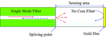
标准的光纤是由涂覆层、 包层和纤芯三部分组成, 而无芯光纤只有石英包层和涂覆层, 而没有纤芯部分。 与常规多模光纤相比, 无芯光纤是通过直接对高纯度玻璃棒拉丝制成, 其各处折射率均相同。 无芯光纤作为传输波导时, 光纤本身充当纤芯、 周围环境介质充当包层构成两层圆光波导结构, 因此无芯光纤对周围环境的参数变化较为敏感。 由于在本研究中所采用的无芯光纤直径大小与普通单模光纤包层直径大小相同, 因此采用剥线钳就可以将NCF的涂覆层轻易剥离掉, 再使用光纤熔接机将无芯光纤一端与单模光纤接续, 而在无芯光纤的另一端面采用磁控溅射方法镀上金膜, 以便增强传感光波信号反射回单模光纤(single-mode fiber, SMF)的光谱强度, 如图1所示。 在液体折射率测量时, 以附着在无芯光纤表面的待测液体作为等效包层形成传输波导。
 | 图1 单模-无芯光纤传感结构Fig.1 The diagram of SM-NCF fiber structure |
根据多模干涉原理, 当入射光由单模光纤耦合进入无芯光纤时, 会在无芯光纤中激发起一系列高阶模式, 这些高阶模式在无芯光纤中传播时相互耦合, 发生干涉现象, 产生能量的不均匀分布。 当入射光波长和无芯光纤的长度满足一定条件时, 将会产生自映像效应, 即入射光自身的再现(包括幅值和相位)[9]。
当无芯光纤的长度变化时, 在光纤末端反射面的光场分布也会随之变化, 进而引起反射光信号强度改变。 当无芯光纤长度为自映像距离时, 其光场能量幅值与入射光信号相同, 且分布较为集中, 此时反射信号的光强也最大。 对于特定长度的无芯光纤, 当采用宽带光源入射时, 光信号从单模光纤传输进入无芯光纤后, 由于各阶传输光模式的能量耦合效率不同, 使得不同波段光波信号产生能量差异, 进而在反射光谱图中呈现出干涉极大值(波峰)或干涉极小值(波谷)分布特征。
由于无芯光纤和单模光纤结构参数的不同, 光信号从单模光纤传输到无芯光纤中时, 最初的纤芯基模将在无芯光纤中激发出若干高阶模式LPmn。 当无芯光纤与单模光纤无偏芯对接时, 由于无芯光纤本身结构具有中心对称性, 使得无芯光纤中只有LP0m模式被激发[10]。 假设无芯光纤中第m阶模式对应光场为Ψ m(r), 根据电磁场连续性条件, 在单模光纤和无芯光纤交界面光场分布为[11]
式(1)中, r为无芯光纤半径, M为无芯光纤中允许存在的模式总数, bm为每个传输模式的激发系数, 表达式为
当光波在无芯光纤中传输L距离后, 其光场分布为
式(3)中, z为光信号在无芯光纤中的传输距离, β m=kneff是第m阶模式的纵向传播常数, neff是无芯光纤的有效折射率。
当光波信号在无芯光纤末端被反射时, 引入反射常数Γ , 反射光信号再次在无芯光纤中传输L距离后的光场分布为[12]
从式(3)和式(4)可以看出, 无芯光纤内部光场分布随传输距离的变化而改变。 传输到无芯光纤末端的光波能量越大, 则反射回来的信号强度就越大, 因此选择合适长度的无芯光纤, 将有利于提高该传感器灵敏度, 这对传感结构的优化设计具有一定的指导作用。 相对于SMS透射型传感结构, 当传感区域长度相同时, SM-NCF反射型结构能够实现对光波信号的往返两次调节。
通过对E'(r, 0)和最初单模光纤中输出的基模光场分布E(r, 0), 使用重叠积分, 得到能量耦合系数的表达式为[12]
能量耦合系数是入射光功率和无芯光纤中某一特定传输模式的耦合功率的函数, 影响着各激发模式功率大小, 从而决定了不同波段反射光波幅值强弱。 因此当光信号从无芯光纤反向耦合回单模光纤后, 耦合光功率表达式为[13]
式(6)中, s0(λ )是宽带光源自身的强度。 当输入特定的宽带光波信号时, 由于每个波长对应的耦合系数不同, 将能够得到具有不同反射光强度分布特征的干涉光谱信号。
无芯光纤中各高阶模式之间相位匹配条件为[14]
式(7)中, N是整数。 当相关传输模式满足该匹配条件时, 耦合效率最低, 反射光谱会出现干涉极小值, 其对应的谐振波长λ 为
由(8)式可知, 反射光谱谐振波长λ 分别与光纤有效折射率neff和光纤长度L密切相关。 当环境折射率一定时, 随着无芯光纤的长度增大, 反射光谱干涉波谷对应的谐振波长λ 逐渐向长波方向移动。 而当无芯光纤长度一定时, 随着环境折射率增大, 各高阶模式之间有效折射率的差值变大[15], 反射光谱谐振波长同样也呈现出向长波方向偏移趋势。
当无芯光纤所处外界环境折射率发生改变时, 其波导结构和包层有效折射率均会发生改变, 从而会引起传输光的纵向传播常数和模场分布发生改变, 最终导致不同波长对应传输光功率的变化。 上述效应反映在反射光谱上, 即干涉波谷对应的谐振波长、 波谷峰值强度以及半波宽度发生相应变化。 通过观测与辨识SM-NCF传感器反射光谱特征参量如谐振波长、 波谷峰值强度以及半波宽度变化情况, 就能够反推出外界环境折射率信息。
采用RSOFT软件, 借助光束传播法对SM-NCF终端反射型光纤传感结构进行数值仿真分析, 得到其内部光场能量分布特征。 首先根据无芯光纤与单模光纤参数建立仿真模型, 对初始光场能量进行归一化处理。 假设输入波长为1 550 nm, 无芯光纤直径是125 μ m, 折射率为1.463。 单模光纤直径为125 μ m, 纤芯折射率1.45, 包层折射率1.447。 仿真时设置输入端单模光纤长度为1 mm, SM-NCF光纤传感结构的内部光场能量分布, 如图2所示。
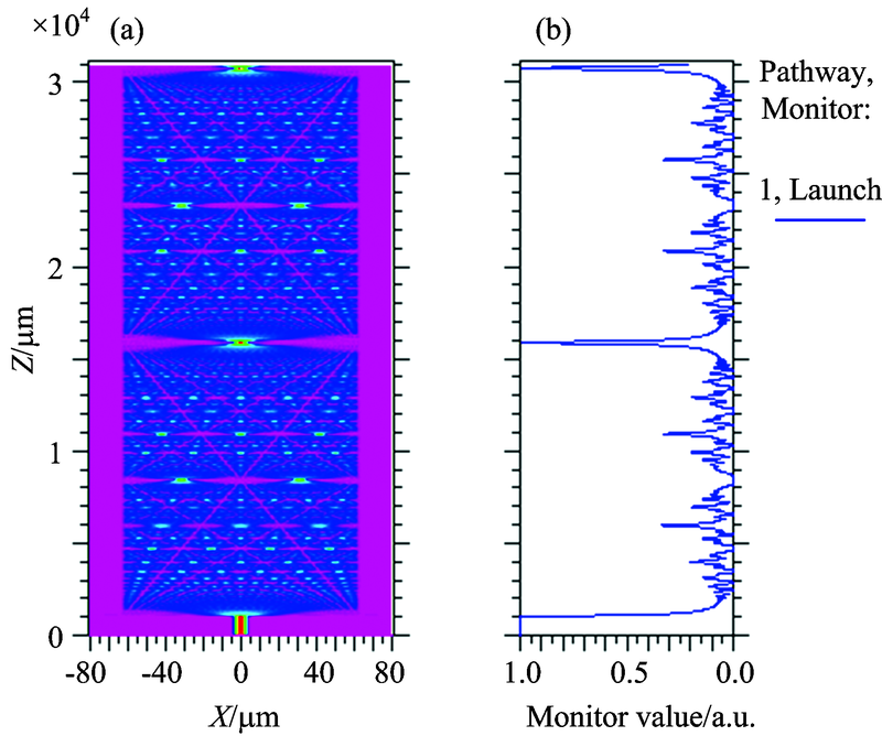 | 图2 无芯光纤内部光场能量分布Fig.2 Energy distribution of light field in NCF |
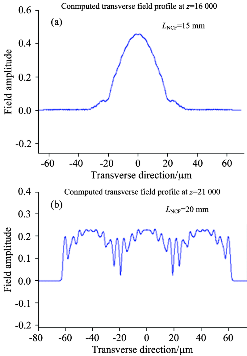 | 图3 自映像和非自映像距离对应的光场分布 (a): 自映像距离15 mm处对应的光场能量分布; (b): 非自映像距离20 mm处对应的光场能量分布Fig.3 The distribution of the light field at the self-image and non-self-image distance respectively (a): The optical field energy distribution corresponding to self-image distance of 15 mm; (b): The optical field energy distribution corresponding to self-image distance of 20 mm |
图2(a)表示为无芯光纤内部的光场能量二维分布情况, 其中x轴表示光纤径向, z轴表示光纤轴向, 可以看到沿无芯光纤轴向分布着明暗不同的光能量点。 图2(b)表示沿光纤轴向的光强幅值大小分布情况。 可以看到, 光波在单模光纤中传输时, 其归一化能量大小始终保持不变。 而当入射光传输至无芯光纤中时, 由于光纤结构的突变, 在无芯光纤中多种高阶传输模式的光信号被激励起来且发生相互耦合。 而纤芯基模与各阶模式的耦合效率存在差异, 导致光能量的分布不均匀, 从而使得某些传输点处能量极大, 某些传输点处能量极小, 这与之前的理论分析相符合, 且这种现象在无芯光纤中呈周期性出现, 即所谓的自映像效应。 根据仿真可得到自映像距离为z=14 880 μ m, 由于在自映像距离处光波能量分布比较集中, 这将有助于增强反射光谱强度。
选择非自映像距离如20 mm的无芯光纤长度作为对比, 在自映像距离和非自映像距离处的无芯光纤的光纤截面光场分布, 如图3所示。 可以发现, 在自映像距离处光纤截面的光波能量呈现集中分布, 而在非自映像距离处光纤截面的光波能量分布较为平坦。
SM-NCF终端反射型光纤折射率传感系统, 如图4所示。 该系统由ASE宽带光源、 AQ6317C型光谱分析仪(光谱分辨率为0.01 nm)、 光环形器、 SM-NCF传感探针、 不同折射率甘油溶液等组成。 实验中将传感探针置于不同折射率甘油溶液, 确保作为传感区域的无芯光纤终端探针完全浸没于甘油溶液。
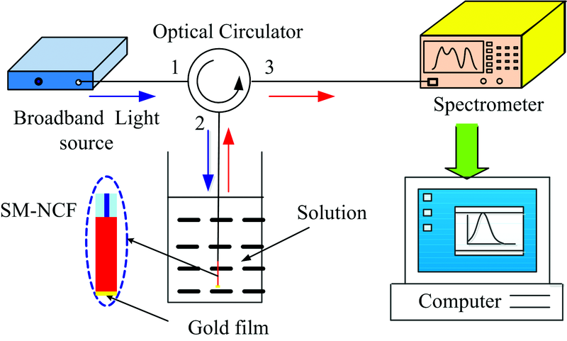 | 图4 实验系统Fig.4 Schematic diagram of the experimental system |
宽带光波信号从光环形器端口1进入, 再由端口2耦合进入SM-NCF传感探针。 反射回来的多模干涉信号又由端口2进, 经由端口3传输至光谱分析仪, 进而得到不同折射率液体对应的反射光谱。 测试系统中光环形器用于保证光波信号单向传输。
每次测量时应将光纤探针在溶液中保持一段时间, 待信号稳定后采集相应反射光谱。 每次更换甘油溶液时, 需用无水乙醇擦拭无芯光纤表面, 以便使其快速恢复至初始状态。
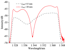
分别将无芯光纤长度为15和20 mm的SM-NCF传感探针放置于蒸馏水中, 其反射光谱如图5所示。
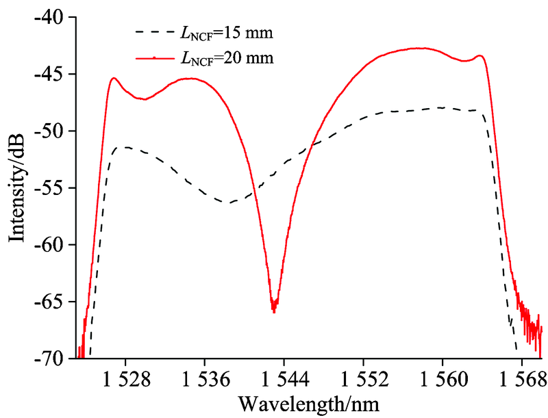 | 图5 不同长度NCF在蒸馏水中反射光谱Fig.5 Reflectance spectra of different length of NCF in water |
由图5可知, 在整个光谱范围内, 当无芯光纤长度为自映像距离15 mm时, 干涉极小值处谐振波长是1 538.6 nm, 谐振峰值强度是-56.313 dB。 而当无芯光纤长度为非自映像距离20 mm时, 干涉极小值处谐振波长是1 542.96 nm, 谐振峰值强度是-65.958 dB, 明显低于自映像距离对应的谐振峰值强度。
当溶液折射率相同时, 随着无芯光纤长度增加, 干涉极小值处谐振峰位逐渐向长波方向偏移, 这与1.2节理论分析相符合。 此外, 其谐振峰半波宽度显著变窄, 也即反射光谱波形更为尖锐。
随着甘油溶液折射率逐渐增大, 由光谱分析仪所采集的15 mm长度无芯光纤探针对应的反射光谱, 如图6所示。
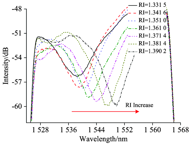 | 图6 NCF长度为15 mm时, 不同折射率 液体对应的反射光谱Fig.6 Reflectance spectra under liquids with different refractive index when the length of the NCF is 15 mm |
由图6可以看到, 在整个光谱图中出现一个明显的干涉极小值, 这是由于无芯光纤中被激励起的多个模式相互干涉与单模和无芯光纤之间的耦合效应共同作用的结果, 而且谐振波长随着溶液折射率增加逐渐向长波方向偏移, 这与之前理论分析相一致。
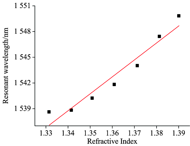 | 图7 NCF长度为15 mm时, 谐振波长与溶液折射率关系Fig.7 Relationship between refractive index and resonant wavelength when the length of NCF is 15 mm |
当传感探针周围溶液折射率从1.331 5增加至1.390 2时, 谐振峰位逐渐向长波方向偏移约11.2 nm。 将该干涉极小值作为谐振波长, 可以得到谐振波长随溶液折射率变化的响应曲线, 如图7所示。 谐振波长λ 和折射率n之间的拟合关系为λ =1 274.018+197.57n, 相关系数r=0.93, 由此折射率灵敏度为197.57 nm· RI-1。
从图6还可以看出随着溶液折射率增大, 反射光信号强度呈现逐渐下降趋势, 如图8所示, 计算得到幅值下降约3.66 dB, 折射率灵敏度为-62.80 dB· RIU-1。 图9所示为反射光谱半波宽度随外界溶液折射率变化曲线, 可以看到溶液折射率较高时半波宽度变化趋于平缓。
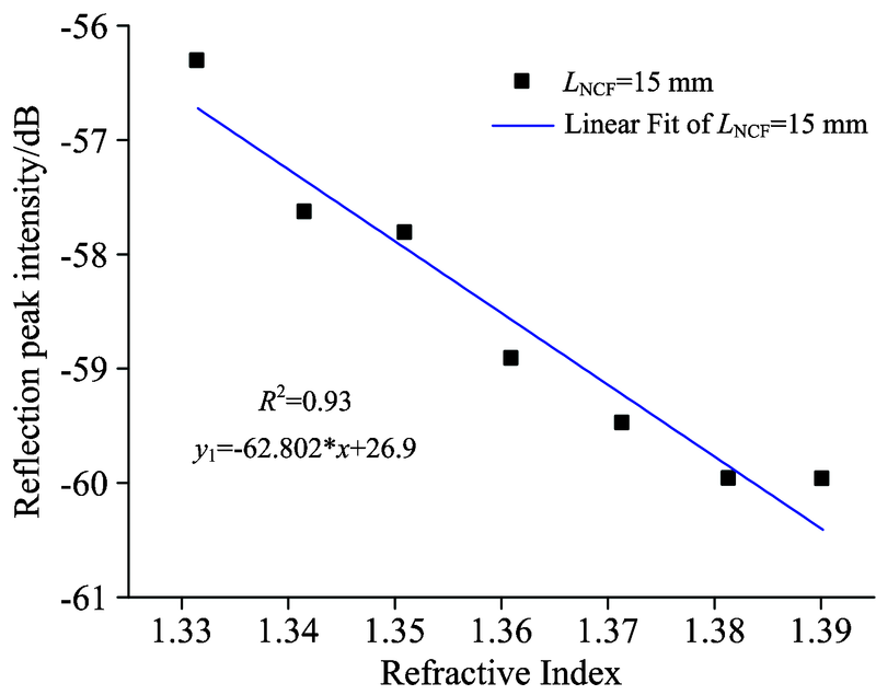 | 图8 NCF长度为15 mm时, 反射峰值 强度与溶液折射率关系3.3 NCF长度为非自映像距离时对应的反射光谱Fig.8 Relationship between peak intensity of reflection and liquid refractive index when length of NCF is 15 mm |
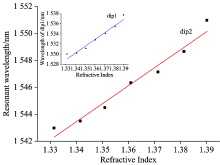
选取无芯光纤长度为非自映像距离20 mm, 由光谱分析仪采集所得不同折射率溶液对应的反射光谱, 如图10所示。 由该图可知, 在整个光谱图中出现了两个干涉极小值(谐振峰谷)。 当传感器周围溶液的折射率从1.331 5增大至1.390 2时, 干涉波谷dip1向长波方向偏移了约7.999 nm, 干涉波谷dip2向长波方向偏移了约8 nm, 可以看出这两个干涉波谷处谐振波长变化趋势大致相同。 谐振波长与溶液折射率之间对应关系, 如图11所示。
 | 图9 半波宽度与溶液折射率对应关系Fig.9 Relationship between half-wave width with refractive index |
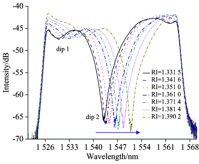 | 图10 NCF长度为20 mm时, 不同折射率液体对应的反射光谱Fig.10 Reflectance spectra under liquids with different refractive index when the length of the NCF is 20 mm |
 | 图11 NCF长度为20 mm, dip1和dip2谐振 波长与溶液折射率关系Fig.11 Relationship between resonant wavelength of dip1 and dip2 with refractive index when length of NCF is 20 mm |
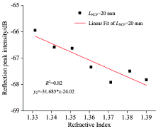
反射光谱谐振波长处的光强随外界溶液折射率变化曲线, 如图12所示。 由图12可以看出, 当选取无芯光纤长度为非自映像距离时, 随着溶液折射率增大, 反射光信号强度呈现下降趋势, 其幅值强度下降了约1.87 dB, 折射率灵敏度为-31.66 dB· RIU-1。
由图11得到谐振波长λ 1和溶液折射率n之间的拟合关系为λ 1=1 352.69+132.47n, 折射率灵敏度为132.47 nm· RIU-1, 相关系数r=0.95。 同样地, 根据图11得到谐振波长λ 2与溶液折射率n之间的拟合曲线为λ 2=1 364.46+133.58n, 相关系数为r=0.96, 折射率灵敏度为134.58 nm· RIU-1。 波谷dip2波形与波谷dip1相比更为尖锐, 且谐振波长灵敏度略高于波谷1, 线性度也较好, 因此选取dip2作为谐振特征波长。
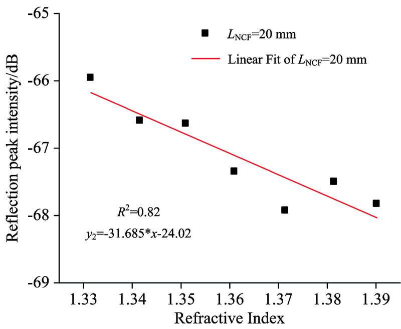 | 图12 NCF长度为20 mm时, 反射峰值强度与液体折射率关系Fig.12 Relationship between peak intensity of reflection and liquid refractive index when length of NCF is 20 mm |
对比分析可知, 不论是从反射峰谐振波长偏移的角度, 还是从反射峰值强度变化的角度, 自映像距离长度对应的SM-NCF终端反射型光纤传感器均具有较高灵敏度, 且无芯光纤长度为自映像距离时对应的反射光谱幅值显著高于非自映像距离, 这为后续实现更高折射率的液体介质测量提供了可能性。
针对生化监测领域高灵敏度特异性检测需求, 研制了一种基于反射光谱特征辨识的单端反射式光纤折射率传感器。 采用无芯光纤代替常规多模光纤, 给出了这种基于多模干涉原理的SM-NCF结构传感机理及其理论模型。
(1)通过数值模拟得到SM-NCF结构在无芯光纤长度分别为自映像距离和非自映像距离时的光场能量分布规律, 可以为光纤传感结构优化提供依据。
(2)当无芯光纤长度为15 mm时, 随着液体折射率逐渐增大, SM-NCF传感光纤反射光谱逐渐向长波方向偏移, 其反射峰谐振波长对应的折射率灵敏度约为197.57 nm· RIU-1, 反射峰值强度也呈现逐渐降低趋势, 其折射率灵敏度约为-62.80 dB· RIU-1。
(3)当无芯光纤长度为20 mm时, 随着液体折射率依次增大, SM-NCF传感光纤反射光谱呈现明显双峰现象, 且均逐渐向长波方向偏移, dip2谐振峰波长折射率灵敏度约为133 nm· RIU-1, 反射峰值强度也呈现逐渐降低趋势, 其折射率灵敏度约为-31.66 dB· RIU-1。
(4)相比于透射型SMS结构, 在传感区域长度相同条件下, 光波信号在SM-NCF反射型传感结构中往返两次被调制, 这不仅利于改善灵敏度, 也有助于减小探针尺寸, 且避免了两次熔接。
(5)这种SM-NCF光纤传感器具有结构简单、 易于制作、 抗电磁干扰能力强以及适合远程遥测等优点。
The authors have declared that no competing interests exist.
| [1] |
|
| [2] |
|
| [3] |
|
| [4] |
|
| [5] |
|
| [6] |
|
| [7] |
|
| [8] |
|
| [9] |
|
| [10] |
|
| [11] |
|
| [12] |
|
| [13] |
|
| [14] |
|
| [15] |
|